A point about total radiated power from these arrays
A comment made by Bill Brown in the post to which I am replying, led me to think of the problem matching the power response of the rings of the array and the central tweeter.
I have tried to ensure that the rings use drivers that are small compared to the wavelength corresponding to the highest frequency. Their power response is therefore predictable, and having multiple radiators in the same band provides control of the radiation pattern. (Also, there's essentially no baffle step to worry about with wide, shallow, speakers against the wall.)
That's in contrast to the central driver which has the usual relationship between power response and on-axis response set by the driver's geometry, and waveguide - if fitted.
Examining the total response of speakers in-room shows that even at locatiions where there are off-axis dips in the response of the array, room reflections provide a relatively smooth total power curve. This may be the reason that such off-axis dips originating from the array are benign compared with the off-axis excess power due to a dome tweeter, for example.
In my latest design, the waveguide is relatively constant directivity over the band in which it dominates. There is a knee or downward steepening in the power response curve where the WG takes over from the array. I guess how this looks is highly depenent on the location of the speakers and the nature of the room.
These comments might give others confidence to continue even if the off-axis direct responses have dips - the result might sound better than you expect.
I had this idea in mind from the start - putting off-axis nulls at angles where particularly strong reflections could be expected. I'm no longer sure how important that choice of where to put the nulls is, as long as the central lobes of the response are wide enough to cover the listening area. I'm unsure how all this interacts with different room shapes and construction, but it seems to work OK in my room.
Ken
Nice points, Ken. I too suspect that good results could be obtained with careful design and verification with measurements.
As I was pondering/drawing out circular arrays I believed that if I could get the surrounding drivers 1/4 lambda away from the central tweeter and 1/4 lambda from each other we would be in good shape in terms of each driver to the central tweeter and each surrounding driver to the adjacent one, but wondered about the surrounding drivers' interaction in relation to the drivers on the other side of the array. That is why I kept returning to the more predictable situation without the circular array.
The first is quite the sentence; hope it makes sense.
Tom Danley's patent suggests it would work.
I would still love to build and measure the large Bliesma tweeter surrounded by SS 10Fs, but phew, that would be $$. Great if it worked (it certainly could), suboptimal if it didn't.
Bill
Bill,
yes, that all makes sense, thanks.
I've always been reluctant to spend big $$ on drivers though I suppose I've bought close on a hundred low $ ones over the decades - arrays help push the numbers up. I do see the technical attraction, however, especially the tweeter. I'm less sure that the 10Fs would be worth the extra (at least with the relative cost compared to the 3FE25s in Europe factor 8+).
Ken
Ken
For sure. The experiment could be done with less expensive drivers (maybe the Faital 3FE?). Also, if the array drivers were used where Ka <= 1, they would be operating as a pure piston, thus less critical. Maybe as long as they don't have breakup anywhere close to the XO.
Bill
Bill
Thanks - I wasn't aware of that study.
I think it is this one
Ken the paper I suggested before is not the right one, that was a mathematical model analysis only, which I worked out when I finally read it

Anyway I have now found the study and got a copy of it, it is this one
AES E-Library >> Experiments in Direct/Reverberant Ratio Modification
Here is the section that was being referred to, PM me if you need more
Attachments

Dips and peaks 1
Fluid, thank you for the excerpt - it matches my experience.
Combined with what I set out in post #101 it's becoming clearer to me how to understand the array. In particular, how the "array of small drivers" kind of in-room power response hands over to the central WG/tweeter's "WG-like" declining power response.
Another requirment is to have some sheilding of the edges of the baffle from ~2kHz radiation, to reduce diffraction which would otherwise be close to the problematic zone.
In my measurements I'd seen little signal with ~1ms delay but I had not done measurements in the plane of the baffle until now today (will post measurement and comments directly).
Even though at the start of the process that led to this thread, having speakers that work against a wall was seen as a constraint, I now regard it as convenient. Effectively extending the baffle to the entire wall is a good idea.
Ken
Dips and peaks 2 - measurement
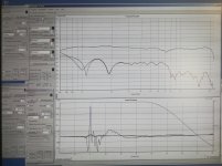
I compared nearfield (~50cm from tweeter) measurements at about 15 degrees off axis (reference) with others in the plane of the baffle, all at tweeter height.
With Holm Impulse, normal gated responses were adjusted such that window reaches zero at about 2ms for all three traces.
Blue (upper curve) - this is the reference.
Red/Green (lower curves) - with outer ring off or on 20cm from edge of baffle, mic tip aligned to the baffle plane. That's ~10cm from the back wall and ~1m from the side wall; reflections from the latter are gated out as are those from the top of the woofer cab on which the speakers sit, the two earliest significant reflections as judged by FR ripples when they are not gated, at least, beyond that come the bigger reflections from the large room surfaces.
It is interesting to see the smooth blend of inner ring and WG even in the plane of the baffle.
The general level in the midrange, at the baffle edge, is ~20dB down from the reference. I've not given this plane much thought before, nor extended simulations out to such large angles, but it seems a good result. I doubt that edge diffraction at this level is a concern in the "sea" of room reflections that come a few ms later.
Dips are due to half-wave cancellations in the array (see green vs red traces above 1kHz). The dips "move around" in frequency depending on both of the angles around the array (altitude and azimuth, etc.). As noted in #101, these average out in the power response as would be expected from an array of point sources, which is a good approximation up to 2 kHz or so.
Ken
Attachments
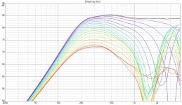
I decided to try and learn a bit more about VituixCAD by simulating the Aura nsw2 (2") driver in a couple of different array configurations. This is using the Enclosure and Diffraction tools to generate a full space response based on the drivers diameter and roll off in an enclosure. This is smoother and more idealized than would be in real life, but the basic principal holds true.
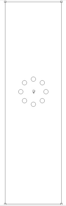
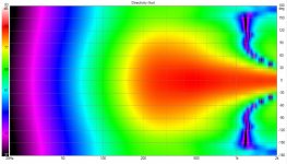
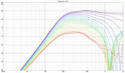
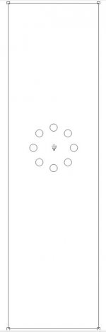
I started with a ring of 8 drivers placed so that a round waveguide of 170mm (Same as Monacor WG300) could fit inside. The baffle is 1800mm tall 500mm wide with a 50mm roundover to help reduce baffle diffraction effects. Virtual mic is 1m height 3m distance.
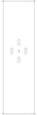
Baffle
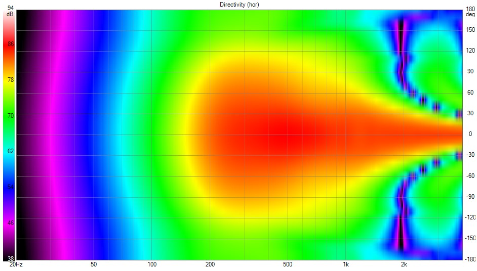
Horizontal

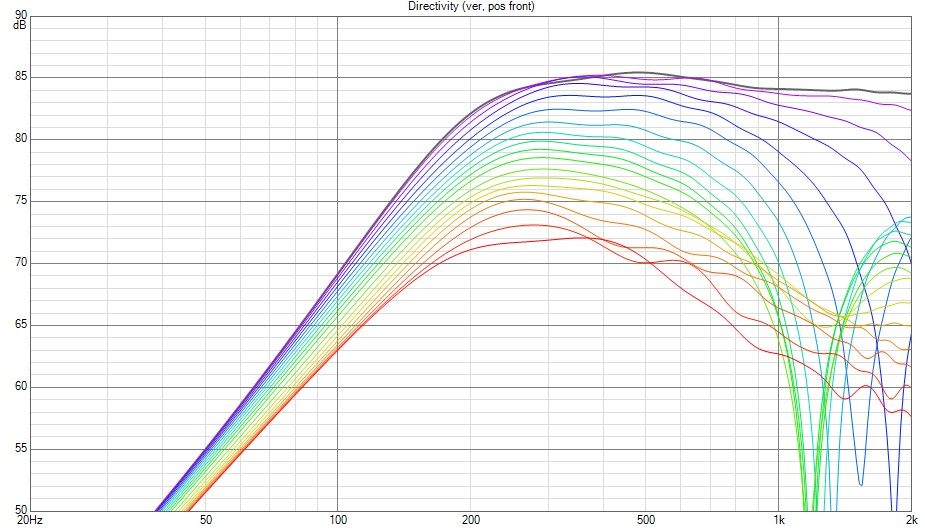
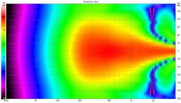
Vertical
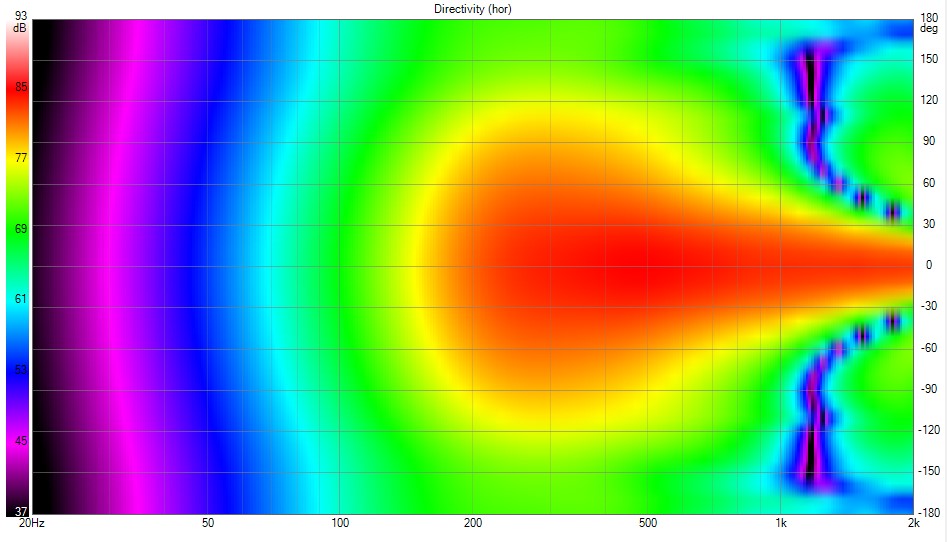
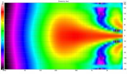
Horizontal Polar
I started with a ring of 8 drivers placed so that a round waveguide of 170mm (Same as Monacor WG300) could fit inside. The baffle is 1800mm tall 500mm wide with a 50mm roundover to help reduce baffle diffraction effects. Virtual mic is 1m height 3m distance.
Baffle
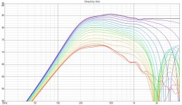
Horizontal
Vertical
Horizontal Polar
Attachments

Squeezing the ring down to be smaller with a 90mm centre space gives this response, more wiggle room to keep the nulls out of the power response but narrower directivity with frequency and more difficulty in finding a driver to match the centre space with a similar directivity.
Horizontal
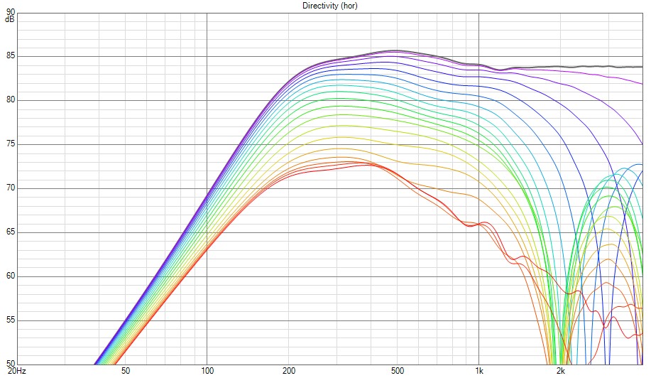
Horizontal Polar
Horizontal
Horizontal Polar
Attachments
Fluid,
good sims, thanks.
They highlight choices: i) equal H &V or V narrower pattern than H and ii) how to blend the tweeter. My conclusion is that both of these are room dependent.
I started out placing too much emphasis on i) I found little to support narrowing the vertical response (in my context, not claiming generality).
I'm glad I made the last array, despite simulations predicting a dip in power response around 1-2kHz. The result, when the room adds its chaos of reflections, is relatively benign, whether measured or, to my taste, on listening.
It could be interesting to find a solution with less of a dip, but all such appear to be complicated or risk introducing other problems. I suspect it could be another decade before I build such a thing.
Ken
Great sims, fluid. Thank you very much.
I have been wanting to do similar with Vituixcad, but don't have a PC.....
Each of the small drivers would have 180 degree radiation up high, so it seems the dips nicely demonstrate the dips based on their interaction in the array only.
If we could cross a tweeter low (and/or or squeeze one in a WG to control directivity) I suspect the power response issues would be mitigated, as Ken has found.
Thanks again,
Bill
Here's the spec sheet i use for BB weight...it matches what I get. https://www.wolstenholme.com/pdf/Baltic Birch Plywood Specifications.pdf
Thanks! Yeah, this stuff varies, my specs normally come from Ga-Pacific since they're local. 😉
GM
reviewing some problems with the ideas explored above
I've been considering the trouble I had with the upper mid drivers in these designs, in both versions but especially the one with ports (low pass filters/Helmholtz resonators).
With ports: unlike ports in the MEH, ports in the first design in this thread are only lightly damped, as the radiation resistance is low. The resonances had Q>10 and damping material didn't help much. To match four of these requires accuracy far beyond what I could achieve.
In the later design with the drivers on the baffle in the usual way, the problem is much less, but the drivers don't quite match which is also annoying in an array which relies on cancellation.
Matching the inner ring of drivers to a waveguide of any sort is a pain. For directivity to low frequency an over-extended horn is probably a better idea, but doesn't fit well with the goal of a speaker that works against the rear wall.
Going to need another decade.
Ken
- Home
- Loudspeakers
- Multi-Way
- After a decade of planning, thanks to forum members