Thanks!
The dimensions are 15.5 x 11.75.
You can get literally any size you want form Landfall.
I ordered the "raw" aluminum because I wanted to get it powder coated originally.
I couldn't find a place to do it reasonably cheap so I ended up giving it a brushed look using 100grit sandpaper.
I may finish it off with wooden panels on the side.. still undecided on that.
If I were to do it over, I'd add maybe 0.5in-1in to the depth to allow more spacing between the power tube and OPT.
Because I experienced some hum in the mock up, I went wider than originally planned to allow for as much space as possible between the OPT's and PT.
I can share an FPD for the top plate if anyone wants. It could be helpful even if you just want the PCB holes.
Last edited:
Hah, you give me too much credit !! I purchased the chassis from Landfall Systems, including the top panel. I must say that this has probably been the BEST experience I have ever had with a vendor and can highly recommend using them.
Their prices are pretty good too.
Initially, I only wanted to order a custom sized aluminum base from them, and then a top plate from Front Panel Express or get a blank plate and drill on my own.
They charged only $25 extra (to the cost of the top plate) for CNC it, all I had to provide was the .FPD file and they did the rest.
One other reason I didnt really want to drill my own was because of the square holes for the Power transformer and power inlet
That's really cheap for the CNC work, I'll have to remember them when I want a custom top. At that price, DIY is not worth it.
To all -
What are your recommendations for brands of 5842? I plan to build a TSEII around 45s and I want to make sure I'm buying smartly.
Thanks
This was a new tube for me as well and based on my restricted research it seems like Amperex, Raytheon and Western Electric 417A are solid choices.
There are some variants that cost more at various tube vendors.
For example, Amperex with Gold Pins or Raytheon's with a windmill getter (whether or not they sound better I have no idea).
I bought some cheap ones from eBay and AES during the build. AES carry them for a decent price but you have to email them to ask which brands they carry.
Based on a different thread here, matched pairs are not needed and in most cases the matching doesn't last anyway.
I can share an FPD for the top plate if anyone wants. It could be helpful even if you just want the PCB holes.
If you are able to. I am always a little envious of some of the finished builds here, metalwork and woodwork are not my strong points - I can do truly impossible things with saws and drills, and not in a good way - so every little bit helps.
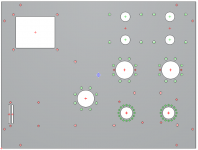
FPD attached. (also attached an image so you get an idea what it is without having to open the zip)
Keep in mind this layout was for the ISO power transformer and EP OPT's.
The PCB layout should be good as-is, unless you use different UX4 sockets that don't have holes for mounting to the top plate.
The PCB area includes the 4 holes for bias adjustment, and selected holes for mounting the PCB with standoffs.
Attachments
Questions regarding a TSE-II in 300B configuration:
1) What is the current rating required for the HV tap? The TSE page states 150mA or more, but that seems a bit low. With 300B's biased at 75-85mA wouldn't that require atleast 190-200mA?
2) Since the 6.3V CT is not used, which 2 connections on the board should be used?
1) What is the current rating required for the HV tap? The TSE page states 150mA or more, but that seems a bit low. With 300B's biased at 75-85mA wouldn't that require atleast 190-200mA?
2) Since the 6.3V CT is not used, which 2 connections on the board should be used?
Regarding ^^, I figured for 300B biased at ~80mA the PT should be atleast 200mA, so will aim for 250mA.
Question for 300B builders- did you use the BOM specified 47uF 450V reservoir cap? With a 330VCT PT, doesnt the voltage exceed 450V in that position?
Question for 300B builders- did you use the BOM specified 47uF 450V reservoir cap? With a 330VCT PT, doesnt the voltage exceed 450V in that position?
I have 300B, Trf:325CT (650v CT toroidal). Output Trf: 3k/70mA. In R30 voltage goes fine, under 400v. Measured friday.
Edited
I prefer to measure B+ in R-OPT2 and L-OPT1. Measured last week. Now i can't do any measure because R5 suddly flashed and got broken. I'm awaiting for a new ohmite resistor.
I prefer to measure B+ in R-OPT2 and L-OPT1. Measured last week. Now i can't do any measure because R5 suddly flashed and got broken. I'm awaiting for a new ohmite resistor.
Last edited:
Yes I expect B+ to be lower than 450V after either Choke/Resistor and load.
I was curious about the 450V rating of C4 which is directly after the rectifier.
I was curious about the 450V rating of C4 which is directly after the rectifier.
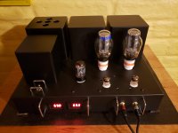
My Finished TSEII
So I started with an SSE, built a second one using KT120s and they both sound great. Recently finished a TSEII and it sounds amazing. Have tried vintage RCA, Mullard and various NOS Military tubes and Golden Lion 300Bs. Outputs are Hammond SE 5000K impedance (the massive ones) and power transformer is Hammond 276X (and also an Edcor of similar specs). Power transformer gets plenty hot over about two hours (hence the vent holes in cover). The chassis is Hammond with some Chinese Ebay covers. Ammeters are a luxury but make life fun. B+ is running about 380 and most of the resistors are Vishay mil-spec and havent seen signs of R5 failing. Do have some really big heat sinks on ICs and a small 12V fan. Thanks George and everyone who posted to this thread to make it possible.
So I started with an SSE, built a second one using KT120s and they both sound great. Recently finished a TSEII and it sounds amazing. Have tried vintage RCA, Mullard and various NOS Military tubes and Golden Lion 300Bs. Outputs are Hammond SE 5000K impedance (the massive ones) and power transformer is Hammond 276X (and also an Edcor of similar specs). Power transformer gets plenty hot over about two hours (hence the vent holes in cover). The chassis is Hammond with some Chinese Ebay covers. Ammeters are a luxury but make life fun. B+ is running about 380 and most of the resistors are Vishay mil-spec and havent seen signs of R5 failing. Do have some really big heat sinks on ICs and a small 12V fan. Thanks George and everyone who posted to this thread to make it possible.
Attachments
I have some Klipsch reference bookshelves and then cheated and added a subwoofer. I would love to have some Scalas someday but not in the current budget.
Thanks itsikhefez for your feedback. Much appreciated.This was a new tube for me as well and based on my restricted research it seems like Amperex, Raytheon and Western Electric 417A are solid choices.
There are some variants that cost more at various tube vendors.
For example, Amperex with Gold Pins or Raytheon's with a windmill getter (whether or not they sound better I have no idea).
I bought some cheap ones from eBay and AES during the build. AES carry them for a decent price but you have to email them to ask which brands they carry.
Based on a different thread here, matched pairs are not needed and in most cases the matching doesn't last anyway.
The problem I'm having is that I can't seem to blow one, even the tiny little 1 watt resistor that blew for two other users blow one.
If it is any help in tracking this down - I cooked this resistor on the original TSE, I was playing around with capacitor values to tweak the B+ at the time and managed to blow both the rectifier tube and one of the bias supply diodes at the same time.
Anybody tried to change cathode resistor on input tube to LEDs or maybe remove that big cap parallel to cathode resistor?
Most 5842's are quite variable in the bias voltage required to get 10 mA of current. We 417A's are a bit more consistent, but both will require some sort of adjustment. You might get by with a big box full of LED's and a lot of patience, but the process will have to be repeated when the tubes are changed. You want to pick an LED that produces about 175 volts on the plate, or 155 to 165 volts for WE317A's. If distortion measurement equipment is available, tune for lowest distortion.
Just removing the cap would reduce the stage gain considerably. Try this only if you have an active line stage or other source with plenty of output.
The particular large cap was chosen by testing a large selection of caps for their important characteristics on an HP component analyzer. That was done 15 years ago, so something better might have come along in the past 15 years.
Feel free to experiment and let us know what you find. The large value was chosen because of it's ESR and ESL characteristics, It doesn't need to be that big, but keep it large enough to avoid phase shift in the lower bass region.
I've read that Organic Polymer caps are good in cathode bypass positions, so I used these
UCC Super Low ESR caps: APSG160ELL102MJB5S
They are rated at 1000uF, 16V with 12mOhm ESR (compared to 90 mOhm of the UPW).
Can't say if they made a difference or not, but the amp works well and sounds great.
UCC Super Low ESR caps: APSG160ELL102MJB5S
They are rated at 1000uF, 16V with 12mOhm ESR (compared to 90 mOhm of the UPW).
Can't say if they made a difference or not, but the amp works well and sounds great.
- Home
- More Vendors...
- Tubelab
- After a 14 year run, the TSE must DIE!