Suzy, I've got 4 x original Hitachi 2SK134's and 2SJ49's for my ETI 477 series5000 rebuild Series 5000 MOSFET stereo power amplifier - Upgrades - Page 3 - DIY Audio Projects - StereoNET that you could borrow 
I just haven't got around to populating the boards yet so you are welcome to use them till I need them ?
I just haven't got around to populating the boards yet so you are welcome to use them till I need them ?
Hi suzyj,
I would be happy to send you a pair (especially receiving an amplifier back 😀), but I think the shipping to Australia would be prohibitive.
Kindest regards,
M
I would be happy to send you a pair (especially receiving an amplifier back 😀), but I think the shipping to Australia would be prohibitive.
Kindest regards,
M
Thanks Leinster Lad! That’d be wonderful. No rush, as I haven’t sent out for boards yet. Still fiddling with rev 1.1 of my lab supply.

Thanks Leinster Lad! That’d be wonderful. No rush, as I haven’t sent out for boards yet. Still fiddling with rev 1.1 of my lab supply.
Would be interested in that lab supply project if you plan to publish it 🙂 I still havent got around to working on my own yet!
Would be interested in that lab supply project if you plan to publish it 🙂 I still havent got around to working on my own yet!
I certainly shall, but wait until I've ironed the wrinkles out. I'm hoping the latest revision (Rev 1.2) is the go.
It's not a cheap build, either.
I certainly shall, but wait until I've ironed the wrinkles out. I'm hoping the latest revision (Rev 1.2) is the go.
It's not a cheap build, either.
Well I have a 500VA toroid core begging to be rewound for some triple output action 🙂 I have a few ideas of my own but nothing stunning on the electronics side... more on the user interface side as I have no trouble getting a microcontroller and lots of C code involved to drive a nice display and knobs 🙂
Sounds lovely. I did originally design it with DACs and ADCs on the board, but I’m really crap at coding, so went with pots. You can still put a 0-5 volt input on where the pot wiper connects and get a 0-100 volt setting.
Sounds lovely. I did originally design it with DACs and ADCs on the board, but I’m really crap at coding, so went with pots. You can still put a 0-5 volt input on where the pot wiper connects and get a 0-100 volt setting.
100V would be a bit out of my comfort zone 🙂 But im sure it'd scale down ! I think I want to try a "totem pole" output arrangement where there's MOSFETs in series, rather than switching taps with relays.
Hey Suzy, have you considered trying out one of the KiCAD plugins that allow you to export an interactive assembly diagram as a .html file? Since you don't really use designators in your silkscreen, this could make assembly easier for people building your designs and might be another step forward in your KiCAD journey 😉 I haven't tried it myself but I was going to use it whenever I publish a design that lacks silkscreen designators. Also interested to see what your lab PSU design looks like!
Interactive KiCAD BOMs Make Hand Assembly A Breeze | Hackaday
Edit: Maybe someone suggested it before (didn't read all the pages in between tbh), but I just used the stuffing diagram that came with the first version of the 50W amp and thought you might be able to improve upon that with very little effort (hopefully).
Last edited:
What a truly wonderful tool.
I've been creating new Fab layer plots today, and building a rev 2 amp (with Renesas TO-3P FETs, as that's actually all I've got in stock - been building too many amps). I put together a shopping cart of double-die Exicon FETs in TO-264 and TO-3, but I'll have to wait until my play money has recovered a bit from buying power supply parts before hitting checkout, or face significant doghouse time.
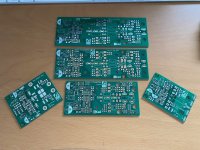
If you look closely at the doco for Rev 1, you'll note that the PCB layouts are a bit clunky. This is because they were done in Protel '98. It's nowhere near as clean to drive as KiCAD. The Rev 2 amp is completely drawn in KiCAD - schematic and PCB, so I can do nice fabrication plots. Like those below:
I've been creating new Fab layer plots today, and building a rev 2 amp (with Renesas TO-3P FETs, as that's actually all I've got in stock - been building too many amps). I put together a shopping cart of double-die Exicon FETs in TO-264 and TO-3, but I'll have to wait until my play money has recovered a bit from buying power supply parts before hitting checkout, or face significant doghouse time.
If you look closely at the doco for Rev 1, you'll note that the PCB layouts are a bit clunky. This is because they were done in Protel '98. It's nowhere near as clean to drive as KiCAD. The Rev 2 amp is completely drawn in KiCAD - schematic and PCB, so I can do nice fabrication plots. Like those below:
Attachments


That tool is so incredibly cool. I shall never print fab layers ever again.
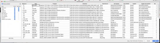
The other one I found was how to edit every single part on the schematic in spreadsheet form, to rapidly build a coherent BOM, with all the detail for everything, without having to tediously open every component. Just go to Tools -> Edit Symbol Fields, and you get a spreadsheet view, ready for copy and paste from your favourite vendor.
The other one I found was how to edit every single part on the schematic in spreadsheet form, to rapidly build a coherent BOM, with all the detail for everything, without having to tediously open every component. Just go to Tools -> Edit Symbol Fields, and you get a spreadsheet view, ready for copy and paste from your favourite vendor.
Attachments

Last edited:
Bought a new bottle of safewash, which I haven’t used in a while.
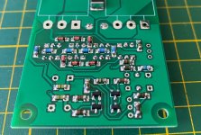
It’s good gear. It (plus SN62 solder and homemade rosin flux) makes for some lovely shiny solder joins.
The new TO-264 boards are coming together rather well. It’s nice to have a helper.
It’s good gear. It (plus SN62 solder and homemade rosin flux) makes for some lovely shiny solder joins.
The new TO-264 boards are coming together rather well. It’s nice to have a helper.
Attachments

Nice station Suzy! It’s time to invest in a microscope, I go cross-eyed with my magnification headgear after a while, LOL!!
What type of container/organizers do you have the SMD parts in? That looks extremely helpful 😉
What type of container/organizers do you have the SMD parts in? That looks extremely helpful 😉
My iron is an old Metcal MX500P. I bought it used on eBay years ago, and the handpiece looked like it'd gone to war, so I bought a new one. Metcal Advanced Soldering and Rework Hand-piece
It's for the newer 5000 and 5200 irons, but is compatible with the MX-500P base and compatible with the same tips the old one used.
My microscope is truly wonderful. It's a Nikon SMZ-645 (again an eBay purchase used) with G-AL 0.7x objective (this moves the focus point to about 150mm from the body, making the ergonomics work really, really well) and a massive boom stand, which sits right at the back of the bench. At full stretch I can get a 500mm wide board under it, and see the front edge.
I keep an eye out for eyepieces, as mine are a little ratty, but so far haven't seen any that hit the right condition/cost number.
My storage system for SMD components is a Licefa A1, from Element14/Farnell. https://au.element14.com/licefa/a1-1-smd-5-bunt/cabinet-5dr-varicol-210-cont/dp/9584331
You used to be able to buy the drawers one at a time, and I had a few, then found they'd discontinued the single drawers and the only way to get them was to buy a stack of 5 in various colours, so I did that at great expense, and now I have lots. I'm thinking of buying another lot soon, as these are getting fairly full.
My phone is a PMG model 801. It still works quite well for receiving calls, but the dialer hasn't worked for years. I'm told I can buy a pulse-DTMF adapter, which I might at some point, as it's a lovely phone - nice and heavy, with excellent audio quaility.
Last edited:
50W Amp TO3 Version:
AEM6000 Based 50W Amp TO3.zip - Google Drive
I've included all KiCad design files, to encourage you lot to try KiCad, plus a BOM in numbers format as well as excel format, plus interactive bom, plus gerbers.
Bear in mind I'm still building this, though the differences from the previous 50W version are very small so I expect it to work without issues. If you want to build it with double-die MOSFETs, you'll have to wait for me to prototype and sort the compensation out - or you could sneak a peek at my 100W amp for where I will start with compensation caps etc.
- Home
- Amplifiers
- Solid State
- AEM6000 Based 50W Amp