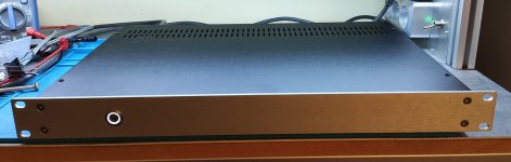
Super cool build Jacques! Really compact using your heatsink arrangement, love the copper look.
Good luck with your newborn and ENJOY the tunes!

Good luck with your newborn and ENJOY the tunes!
Hello,
very interessting project, no symasym or mutations of that and with avaiable MOSFETs.
It seems easy to build and the MELFs make the board unbelievable small. This is what I was looking for. Very suitabel to home cinema with uncountable channels. --> Thanks to suzyj!
Unfortunatly there are two disadvantages for me: SST404 und MMBTAx are no common components in Germany.
Greetings, Mat
I believe BC816/806 would be perfect substitutes for the MMBT parts.

It sounds much better than it looks.
The biggest difference with my other diy amps resides in the restitution of percussion sound details in the higher spectrum, especially cymbals.
I have the impression to suddenly discover new instruments in pieces I listened to for years.
On the other hand, lower quality recordings now sound incredibly dull in comparison.
Last edited:
I'd settle for clinical, as that's the intent 😛
Did anybody perform measurements such as harmonics profile?
I admit I haven’t really measured the 50W one that much, but I measured its 100W friend to death: Suzy's Blog: Measuring a MOSFET Power Amplifier.
You could, but it wouldn't be neat, as the distance between the hole and the pins is a lot longer on the TO-264 package vs the TO-3P package, which this amp is designed around.
You would have to space the PCB up a bit off the transistors to account for the overlap where there are through-hole parts, and assemble it by mounting the transistors to their heatsink and soldering them to the PCB afterwards, as there would be no way to get to the mounting screw for the transistors.
You would have to space the PCB up a bit off the transistors to account for the overlap where there are through-hole parts, and assemble it by mounting the transistors to their heatsink and soldering them to the PCB afterwards, as there would be no way to get to the mounting screw for the transistors.
So...
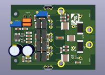
If you swap the Zobel resistor for a 1W MELF, that allows you to move it to the underside, which then allows you to move the TO-264 parts a bit closer together. Careful examination of the 3D modelling shows that the package has a handy notch in it, which can be used for the source resistor pins, as long as you go from a 20.32 to 25.4mm pin pitch, which you're really going to want to anyway as you'll want a higher power resistor for the sources.
So then the rest of the components have a bit less space due to the additional length of the TO-264. That can be accommodated by swapping the input cap from an MKS4 package to an MKS2 package, and a little bit of rework of the layout.
At the same time admit that mica caps aren't required, and use 1206 ceramics, and use the newer footprint for 1206, MELF resistor, and MELF diode with slightly easier to solder pads. Make the pads on the other components a teensy bit bigger (=easier to hand solder) as well, and put bigger 6.35mm spade connectors in for the high-current connections...
While there, reverse the trimpots, so they adjust in the expected direction (clockwise = more positive). I was going to swap the SOT-23 parts out for TO-92, but that's a bigger challenge.
By which I'm saying that the new version of KiCad is such a bloody dream to work with that I can knock a board respin like this out in a (long) evening's work.
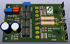
Celebrate by sticking the new logo on it, to better utilise the space created on top-layer by the loooong TO-264 package.
Et voila. A 50W amp on a 50x75 board that accommodates double-die Lateral MOSFETs, as well as the ordinary ones if that's desired. It may be good for slightly more than 50W.
If you swap the Zobel resistor for a 1W MELF, that allows you to move it to the underside, which then allows you to move the TO-264 parts a bit closer together. Careful examination of the 3D modelling shows that the package has a handy notch in it, which can be used for the source resistor pins, as long as you go from a 20.32 to 25.4mm pin pitch, which you're really going to want to anyway as you'll want a higher power resistor for the sources.
So then the rest of the components have a bit less space due to the additional length of the TO-264. That can be accommodated by swapping the input cap from an MKS4 package to an MKS2 package, and a little bit of rework of the layout.
At the same time admit that mica caps aren't required, and use 1206 ceramics, and use the newer footprint for 1206, MELF resistor, and MELF diode with slightly easier to solder pads. Make the pads on the other components a teensy bit bigger (=easier to hand solder) as well, and put bigger 6.35mm spade connectors in for the high-current connections...
While there, reverse the trimpots, so they adjust in the expected direction (clockwise = more positive). I was going to swap the SOT-23 parts out for TO-92, but that's a bigger challenge.
By which I'm saying that the new version of KiCad is such a bloody dream to work with that I can knock a board respin like this out in a (long) evening's work.
Celebrate by sticking the new logo on it, to better utilise the space created on top-layer by the loooong TO-264 package.
Et voila. A 50W amp on a 50x75 board that accommodates double-die Lateral MOSFETs, as well as the ordinary ones if that's desired. It may be good for slightly more than 50W.
Attachments
Last edited:
Sure, but let me sleep first. Releasing gerbers at 1am after a marathon design session = mistakes, and I really don't want that.
Have you thought of skipping the source resistors altogether? I've built plenty of lateral mosfet amps like that and the output stages have behaved well. Thermally it allows an interesting option. The output devices can be mounted directly to a copper heat spreader which is then insulated from the heatsink. This lowers thermal resistance between the output stage and heatsink considerably.
I'd love a TO-3 version of these, but that's too much to ask. Maybe one day I'll be able to take the gerbers and modify it myself (maybe...). I imagine it would also be worth trying to run short wires to the outputs, especially if the gate resistors are placed right at the gate pin.
I have also seen lateral designs without source resistors.
I have also seen lateral designs without source resistors.
I'd love a TO-3 version of these, but that's too much to ask. Maybe one day I'll be able to take the gerbers and modify it myself (maybe...). I imagine it would also be worth trying to run short wires to the outputs, especially if the gate resistors are placed right at the gate pin.
I have also seen lateral designs without source resistors.
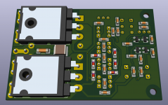
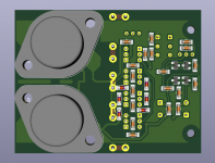
Mmmm... Surface mount source resistors maybe? Nothing's impossible. Here's a very rough idea of what it might look like. A bit of shuffling is still needed, but so far it's 75mm x 58mm.
Attachments
- Home
- Amplifiers
- Solid State
- AEM6000 Based 50W Amp