Wow! You're amazingly fast! Thank you for at least considering it. You don't have to spend more time on it if you don't think it's really feasible, or practical.
What about a substitute SST404-LF for something a little more common too?
Is it sacrilege to suggest optional pads for two TO-92 type 2SK170 transistors? IDSS of 3.5mA might be harder to find though. I have some around 9mA
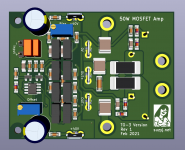
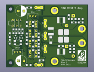
Gerbers for the TO-264 version are at: AEM6000 Based 50W Amp Rev 2 Gerbers.zip - Google Drive
I won't substitute out the SST404. It's way too important to the performance.
I won't substitute out the SST404. It's way too important to the performance.
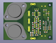
And here's where the TO-3 version is at. I think that's probably a goer. I'll check over it in the morning and then post up Gerbers tomorrow. There's something particularly weird about mixing TO3 with SMD.
Attachments


Very nice. Again, don't bother if it's too weird or doesn't make sense to do this one! 🙂
Couple of questions:
1) Are the gate resistors back beside the bias pot? Is that close enough to the gate pins? (I've often read for laterals to have them as close as possible, but I'm not an expert. And, it probably is pretty close as this is such a small pcb.
2) I believe the pins on the TO-3 are gate and drain, not gate and source, or am I misinterpreting the diagrams.
Thank you for what you've done so far, and don't feel bad if you don't want to continue on this one.
Steve.
Hey Steve, very nice catch - thatnks for picking that up. I'd assumed the pinout of the TO3 was the same as the TO3P (1 gate, 2 drain, 3 source), but it makes sense that the body is source as it's a lateral.
I've also moved the gate resistors, plus added pours for the +40V and -40V terminals on board top, just to ensure no other pours get in between the pins.
This new version of KiCad is _so fast_ to design in, as is no doubt evident by how quickly I've been producing boards in the last few weeks. It's like I have an idea, I draw the idea. The tools help rather than hinder. I'm probably sounding like a broken record here, but I've used many different PCB CAD systems over my career, and this is by far the best one I've ever used. And it's FREE!!!
Also I found a cool resistor that I can use for sources. It's allegedly 7W in a 7.1 x 4.6mm package, and really low inductance to boot. See https://au.mouser.com/datasheet/2/427/wshm2818-1762134.pdf
And here's the Gerbers, as promised.
AEM6000 based 50W Amp TO-3 Gerbers.zip - Google Drive
Again, please bear in mind that it's completely untested, as with the TO-264 version.
Also as with the TO-264 version, it may do slightly more than 50W.
Attachments

Last edited:
Thank you so much! I have accumulated quite a few TO-3's over the years, so I'll give this a try. I'll add it onto my next pcb order, but it will probably be a while before I get it built up. Thank you once again! 

I must give KiCAD another go.. but the past few times ive tried it, i've found it to be clunky garbage and gone straight back to EAGLE (pre-Autodesk)
It's a pity 2SK2145 has one side of the JFETs commoned... it looks like a good little part otherwise
It's a pity 2SK2145 has one side of the JFETs commoned... it looks like a good little part otherwise
Suzy , according your manual 40Vdc is the most ideal rail voltage . Can I use 50 - 51Vdc without component value change .
Or I can go for 38Vdc , have some Nice R Core (Selectronic )Transformers for that .
Or I can go for 38Vdc , have some Nice R Core (Selectronic )Transformers for that .
Last edited:
It rather depends on your speakers and heatsinking. 50V is a bit much, especially with lower impedance speakers.
I’d go for 38.
I’d go for 38.
Will go for the 38Vdc than , only it's a 400 VA .
More than enough!
There's something particularly weird about mixing TO3 with SMD.
Tell that to folks who take a diet Coke with their Big Mac and large fries... 😀
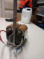
What is the part number for those TO3s ?
Several could be used. Hitachi lateral mosfet pairs including 2SK133/2SJ48, 2KS134/2SJ49, 2SK135/2SJ50 (and perhaps even the K175/J55 or K176/J56 pairs).
Profusion also sell the Exicon versions of these which are still being manufactured.
Hi spind,
yours is a timely post as I have a few 2SK135/2SJ50.
As you seem to be knowledgeable, would I have to change anything as far as the output transistor circuitry (C9, C11, R44) is concerned? I am asking because Borbely Servo 100 using these transistors has 330 pf in position of C9 and nothing as far as the other FET is concerned.
Kindest regards,
M
M
I’m doing a board run in the next week or so. I shall include some of the double-die TO-264 and TO-3 ones.
However I don’t have any TO-3 transistors to prototype with. I’ll buy some Exicon ones, but would like to check performance with some older Hitachi parts. Anyone willing to lend me some for development?
However I don’t have any TO-3 transistors to prototype with. I’ll buy some Exicon ones, but would like to check performance with some older Hitachi parts. Anyone willing to lend me some for development?
- Home
- Amplifiers
- Solid State
- AEM6000 Based 50W Amp