
Suzy is already providing all the gerbers here so that you (or Prasi 🙂) do not have to reinvent the wheel.Can you help draw a PCB?
sorry man, cant put in time and effort on this right now.
on a side note: this schematic is slightly different compared to the gerber folder. are you sure this is correct one?
Yes, I suspect the take off point for the second diff pair base is taken from the emitter of Q2 the right side rather than the collector.
This is SGViper's post of #240.
HD
This is SGViper's post of #240.
HD
Last edited:
Hi Sgviper,
If you have the complete AEM6000 article, could you please post it here?
Thnks,
Jacques
If you have the complete AEM6000 article, could you please post it here?
Thnks,
Jacques
The layout was redesigned to be fully compatible with TO3 and TO247View attachment 1074266View attachment 1074270
Any update on a PCB?
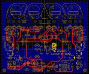
Just according to the original SCH, see the original picture of the PCB drawing, there is no change.
This is the layout that has been modified for many times and has not been verified. If any mistakes are found, please guide me. Thank you

Thanks Suzy for keeping this beautiful instrumentation amplifier alive, there are old and new instrumentation equipment's still using this topology. I think I still have your LTSpice files from way back then. Did you ever make a phono preamp using this topology? Do you prefer the instrumentation amplifier over an audio amplifier? But it sure would kick *** in a phono preamp. You should hook up with Wayne to give us the ultimate phono preamp featuring steep low noise filters
Hi Suzy, just found the description expected of an instrumentation amplifier in your documentation. The spectrum analyzer results further reinforces the narrative. "The end result is a robust, dependable, fast, quiet and reasonably cool amplifier, that has been (disparagingly) referred to as clinical. To my mind this is exactly what an amplifier should be. I’ve had half a dozen in near constant use for years, driving for example my Ariel transmission line speakers, my original noisePlank, noiseUnit (in prototyping), a pair of Infinity RS-5b speakers, and some DIYAudio “reference” speakers. It’s my go-to amplifier."
Suzy's amp looks really nice. i'm really curious, both mosfet, jfet and clinical sound. I have a lot of exicon mosfet stock. I will start 50w Rev2 version in this week. I am also like to work with melf resistor like her 🙂
If somebody is interested, i am working on a mouser BOM (latest 4th revision as indicated prior in the thread). I imported SuzyJ's BOM but had to adapt several items as I did not want to order 3000 or 4000 capacitors 🙂 I would post it when ready.
By the way a big thanks to SuzyJ for the really great documentation. I also ordered 10 boards (black) @jlcpcb.
By the way a big thanks to SuzyJ for the really great documentation. I also ordered 10 boards (black) @jlcpcb.
Can I reduce the power supply voltage to +/-15V and use it as a headphone amp? As the document stated, the load resistor need to be changed. Which value should they be if I bias the output mosfet at 120mA and drive 32ohm headphone with it?
- Home
- Amplifiers
- Solid State
- AEM6000 Based 50W Amp