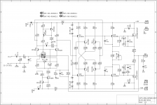
hi prasi:
It looks like all the diodes are backwards
no way man.. not as per suzyj's sch
Attachments

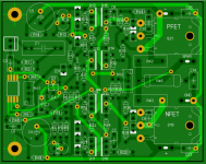
My through-hole version using a double-sided board is attached. 68 x 85mm.
1. I have used BCXXX series for the non-Q3/Q4 signal transistor types which is why the pins are different.
2. The MOSFETs bolt thru the board so the whole board is also not hanging on the MOSFET leads. Also, no copper is under the board where the MOSFETs mount to provide the cleanest, flattest surface.
3. The drivers and MJEXXX's are able to be mounted on a central heatsink. Q16 and Q18 in particular, will probably need this heat sink at higher bias currents.
4. The dual FET input uses a SOIC8-W. I need to double check that case type.
5. All but the Zobel and output resistors are 1/4 W types which allows 8mm hole spacing.
6. Rail electro caps can be up to 12mm diameter.
I haven't done a final wiring check but expect that it should be 99% correct.
[/ATTACH]
Attachments
tcd1963,
This looks very promising. I’m curious what SST404 substitute(s) are you targeting? I did not see a reply from Suzy to Prasi’s question of the same nature, although she said “sure” to 2N5564/5565/5566 - matched pairs of JFETs mounted in a TO-71 package.
This looks very promising. I’m curious what SST404 substitute(s) are you targeting? I did not see a reply from Suzy to Prasi’s question of the same nature, although she said “sure” to 2N5564/5565/5566 - matched pairs of JFETs mounted in a TO-71 package.
Last edited:
The basic SST404 is the same dual FET device as in the original design. The U404 is the same but in a through-hole TO-71 can.
Some vendors say that the SST404 is obsolete but i haven't seen any say that about the U404. My design is for the SST404 which i think should still be available from some suppliers. Adding a few extra t/h pads for the U404 wouldn't be hard.
Some vendors say that the SST404 is obsolete but i haven't seen any say that about the U404. My design is for the SST404 which i think should still be available from some suppliers. Adding a few extra t/h pads for the U404 wouldn't be hard.
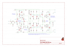
hi prasi:
It looks like all the diodes are backwards
did we just see a Chinese Xerox system ghost? mass production may be with ultra cheap kits? I am purely guessing, I may be wrong😀
I did not see a reply from Suzy to Prasi’s question of the same nature, although she said “sure” to 2N5564/5565/5566 - matched pairs of JFETs mounted in a TO-71 package.
I know SST404s work well. U404s also work well, as they’re the same die in a different package. I have a whole pile of SST404s, and know I can get more from Future electronics whenever I want. For the record, I have to order these internationally just like you do.
I’m pretty patient, but not patient enough to pore through the data for every random jfet that people feel like suggesting. If you’re keen on a particular device then do the work yourself. Check the data, run a simulation. Even try building one around it.
Then you’ll be making a valuable contribution.
My design is for the SST404 which i think should still be available from some suppliers. Adding a few extra t/h pads for the U404 wouldn't be hard.
tcd1963,
Thanks for your reply to my question regarding your targeted jfet device(s). The extra pads to allow for the use of U404 would likely help potential builders that have difficulty sourcing SST404 (if you plan to share our board design).
I have created 2 versions because i had difficulty fitting the narrow body SOIC8 around the TO-71 pins. It was possible, but I was not happy with the clearances. ...when it comes to making boards with tight fitting thru-hole devices, good eyesight, a steady hand and a very small solder tip are needed, none of which I can profess to have!
I will share the Sprint file tomorrow.
Also, I have changed the spacing between opposite TO-126 transistors where the heatsink could go. I dont have a standard spec for aluminium so this spacing might be too large. it is currently 2.78 mm which after taking into account insulators, is a fairly thick piece of Al. Suggestions are welcome.
Last edited:
Attached is the zipped Sprint Layout 6 file. It contains 2 boards - TO-71 and SOIC8 versions. Feel free to use this. Check all traces for correctness etc before using.
View attachment AEM6000mod.lay6.zip
View attachment AEM6000mod.lay6.zip
Any chance of a 100W TH version ?
With the same schematics and double-die latfets, you should be able to get 100W.
That's what I was thinking. The gate resistor values might need changing but otherwise the footprint could be the same.
The P and N channel Exicon dual die devices have quite different gate capacitances (unlike the single die devices) so the gate resistors might be quite different to each other and those gate capacitances are also much higher than the single die devices.
The P and N channel Exicon dual die devices have quite different gate capacitances (unlike the single die devices) so the gate resistors might be quite different to each other and those gate capacitances are also much higher than the single die devices.
I have made some changes to the layout to address the return ground traces which were going to the main ground and not to the signal input ground.
I have also tidied up some of the component spacing etc. Attached is the updated and compressed Sprint Layout file which contains layouts for both TO-71 and SOIC8 input chip packages.
View attachment AEM6000mod.lay.zip
I have also tidied up some of the component spacing etc. Attached is the updated and compressed Sprint Layout file which contains layouts for both TO-71 and SOIC8 input chip packages.
View attachment AEM6000mod.lay.zip
- Home
- Amplifiers
- Solid State
- AEM6000 Based 50W Amp