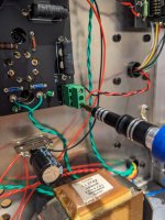
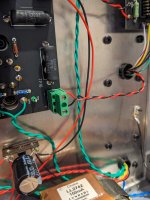
I was taking some measurements of Aegis today when I realized that I had made an error in the build instructions. The intention of the circuit is to maintain absolute signal polarity from input to output. This is done by wiring the primary and secondary of the output transformer in opposite polarity since a cathode follower stage is non signal inverting. However, as built, this is not the case, I wrote the instructions to wire the output transformer primary and secondary with the same polarity by mistake. The audibility of absolute signal polarity is debatable, but it is very simple to fix, so here is what you need to do.
1) If you are thinking about building this amplifier or are acquiring parts but have not yet ordered the ELMA switch PCB, I've uploaded a new PCB gerber file to the diyAudio page. The error is corrected on the new PCB and the instructions can be followed as written.
2) If you've already built or own an Aegis, or have already ordered the old ELMA switch PCB, you will need to do the following.
- Find the screw terminal where the output transformer wires (pins 13 and 18) connect to the main PCB. Loosen the screw terminals and flip the wires such that the red wire (pin 18) goes to the negative (-) screw terminal and the black wire goes to the positive (+) screw terminal. Retighten the screws. Repeat the process for the other channel.


That's it, then the polarity is corrected. As I mentioned, the audibility here is very questionable. I A-B'd in both orientations with alligator clips. I thought maybe the corrected polarity sounded better, but honestly in a blind test I'd never be able to tell them apart. It's just a matter of principle as this was how the circuit was supposed to be built.
Anyway, sorry for the inconvenience, hope it isn't too much of a hassle to do this flip flop. As I said, with the issue corrected on the new ELMA switch PCB, any build going forward can simply follow the original instructions. If you have the old ELMA PCB but have not built yet, you will need to do this fix as well.
1) If you are thinking about building this amplifier or are acquiring parts but have not yet ordered the ELMA switch PCB, I've uploaded a new PCB gerber file to the diyAudio page. The error is corrected on the new PCB and the instructions can be followed as written.
2) If you've already built or own an Aegis, or have already ordered the old ELMA switch PCB, you will need to do the following.
- Find the screw terminal where the output transformer wires (pins 13 and 18) connect to the main PCB. Loosen the screw terminals and flip the wires such that the red wire (pin 18) goes to the negative (-) screw terminal and the black wire goes to the positive (+) screw terminal. Retighten the screws. Repeat the process for the other channel.


That's it, then the polarity is corrected. As I mentioned, the audibility here is very questionable. I A-B'd in both orientations with alligator clips. I thought maybe the corrected polarity sounded better, but honestly in a blind test I'd never be able to tell them apart. It's just a matter of principle as this was how the circuit was supposed to be built.
Anyway, sorry for the inconvenience, hope it isn't too much of a hassle to do this flip flop. As I said, with the issue corrected on the new ELMA switch PCB, any build going forward can simply follow the original instructions. If you have the old ELMA PCB but have not built yet, you will need to do this fix as well.
Hello,
What is the purpose of the 4.7k resistor on the elma switch board ? Is it mandatory ? Can the ll2765 be used just as it is ?
Thanks
What is the purpose of the 4.7k resistor on the elma switch board ? Is it mandatory ? Can the ll2765 be used just as it is ?
Thanks
Ok, thanks. I have a Dan Clark Aeon 2 Noire which impedance is 13 ohms (flat). Will it work on the Aegis?
Output Z on the low impedance setting is 5ohm with EL34, so you'd be looking at a damping ratio of a little over 2:1. It'll work but I can't comment on how well they'll pair with a very low impedance planar.
You are right - I am going to leave it.
For my planar headphones, could I use a 20 ohms serie resistor ?
For my planar headphones, could I use a 20 ohms serie resistor ?
The resistor isn't in series, it's in parallel. So with a 13 ohm headphone, it is sonically invisible. The only concern with your planar is that it is a low impedance headphone, so the damping ratios are only 2:1. That doesn't necessarily mean it will sound bad, it could still sound great, it's just not one that I've tested specifically.
Yes, I keep the 4.7k in parallel - but what about also using a 20 ohms resistor in série with my planar ? Thanks
To fit the 32r recommended in the ll2765 file ? Not a good idea ? Better to let the ll2765 see 13r ?
IMO yes, the reflected impedance to the primary will be lower, but given the output tube is in cathode follower configuration, it is not likely to drastically affect the frequency response. Putting a 20ohm resistor in series with the headphone would be much worse.
for those who are perhaps thinking about building the Aegis, I currently have two complete sets of Lundahl transformers for the Aegis kit on hand ready for immediate shipping.
You can contact me via the web site or 'pm' me.
You can contact me via the web site or 'pm' me.
I would take a Lundhall tramsfo kit, if you have one in stock, just sent you an email. Thanks
SB
SB
for those who are perhaps thinking about building the Aegis, I currently have one complete set of Lundahl transformers for the Aegis kit on hand ready for immediate shipping.
You can contact me via the web site or 'pm' me.
You can contact me via the web site or 'pm' me.
- Home
- Amplifiers
- Tubes / Valves
- Aegis DIY Tube Headphone Amplifier