Frankly you have way too much power here if you have 200w amp on 110db speakers. You are one volume control accident away from permanent hearing damage. No wonder it's hissy. IMHO you need to rethink the amplifier selection.

Best answer I'd say, you can choose the exact gain you want as well as bring down distortion. Just mind the input impedance 👍Because this design's gain is quite more than just 0.6!
One could increase the value of R23 and put a resistor from the output to pin 7. This also would cure the issue of the lacking 1st triode grid leak.
Best regards!
Yes, an anode follower. Adding a cathode follower to buffer it is a good idea too.
The series resistor in the NFB divider sets the input impedance, so 100k or 51k are reasonable choices for that part.
And so on and so forth...
The series resistor in the NFB divider sets the input impedance, so 100k or 51k are reasonable choices for that part.
And so on and so forth...
My idea is the pot on output of 47 k linear ( not 22 k due the Zin of amp) one for channel high level is the best way
This because there is a pot in input so the setting of the out can be regulated in the best way
Walter
This because there is a pot in input so the setting of the out can be regulated in the best way
Walter
You need to define the goal: The volume control at the output results in higher distortions, higher output impedance, and lower headroom, but low noise. Put at the input leads to probably higher noise figures, without the other disadvantages. What do you prefer?
As a compromise, you can chose the volume control potentiometer as part of the NFB divider.
Best regards!
As a compromise, you can chose the volume control potentiometer as part of the NFB divider.
Best regards!
He already has the pot on input as wrote post agoYou need to define the goal: The volume control at the output results in higher distortions, higher output impedance, and lower headroom, but low noise
Yes, both channels hissing. I don't have hiss with my ss preamp with similar gain, so I assume it's the tube. The hiss is the main issue. Lower gain will just be an added benefit. Reducing the gain with -10 dB would be good.
The problem is that my speakers are 110 dB/W and the power amp is 29dB gain. I reduced the output voltage from my dac IV so it works with overall volume. But any noise from the pre will be very audible.
Attennuation in the DACs digital domain reduce the number of bits and that is not good. Keep attenuation in the analog domain.
With that high sensitivity of your loudspeaker and a gain of 28 times I would suggest a passive preamp with only attenuator if your power amplifier have high input impedance.
Why not just use a cathode follower in the tube section if you don't need the gain?
To solve quickly and fine the problemYes. But what then was the purpose of your post #44?
How's this for a compromise?

Cathode follower using paralleled 12AU7, cathode biased. Volume control on the output.
Or this?

Cathode follower using paralleled 12AU7, 'silent bias' (fixed bias). Volume control on the output.
Perhaps the volume control pot should be a lower value. 50k? 25k? 10k?
Cathode follower using paralleled 12AU7, cathode biased. Volume control on the output.
Or this?
Cathode follower using paralleled 12AU7, 'silent bias' (fixed bias). Volume control on the output.
Perhaps the volume control pot should be a lower value. 50k? 25k? 10k?
It looks like you can buy this kind of thing off the shelf, for $109 USD.
https://apos.audio/products/xduoo-mt-603-multichoice-pre-amp

It's made with electrolytic caps, SMD resistors and a switch-mode boost converter for the B+, but it sure looks like it's a 12AU7 cathode follower with input selector switch. No volume contol, though. But that's not needed with a unity gain buffer.
If you build your own you can use boutique parts and a big, old-style linear power supply.
https://apos.audio/products/xduoo-mt-603-multichoice-pre-amp
It's made with electrolytic caps, SMD resistors and a switch-mode boost converter for the B+, but it sure looks like it's a 12AU7 cathode follower with input selector switch. No volume contol, though. But that's not needed with a unity gain buffer.
If you build your own you can use boutique parts and a big, old-style linear power supply.
Need to see power supply. The 12au7 heater cathode voltage of 100...then it breaks, so you have to raise the heater at least to 50
I would raise the heater bias to +80V.
One could also redesign the power supply to lower its voltage to +250V, which would allow for more filtering/decoupling stages, better ripple rejection.
All we know is that the original schematic says the B+ is +320V. I remember something about the heater supply being 6.3V, but I don't know if that's AC or DC. We don't know anything else about the power supply, at least not that I'm aware of.
Those are PCB layout diagrams, not schematics, so we still don't know exactly what's going on. But we can infer some basic characteristics.
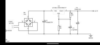
1. It looks like both the B+ and the Heater (HTR) supplies are regulated. Are VD1-VD10 zener diodes? The HTR supply looks like your basic LM317 regulator.
2. For the HTR supply, there's a pad for "HGND". That's probably a floating ground connection for the 6.3VDC supply. If that's correct, that could be connected to the center (node) of a voltage divider (two resistors from B+ to ground with a capacitor bypassing the 'bottom' resistor) to bias the heaters to the desired DC voltage.
Last edited:

In the heater supply, is the node HGND connected directly to 0V? Can it be connected to something else?
If so, you could connect that HGND node to the junction of R31 and R32 in the B+ supply, to keep a 12AU7 cathode follower within the cathode-to-heater voltage limit (usually thought to be 100V but some say 200V for 12AU7). On the B+ supply, the voltage at the junction of R31 and R32 should be about +76V DC.
The B+ supply looks like a capacitance multiplier with zener stabilization, with a CCS to the zener string. Looks OK to me, but I didn't check it thoroughly. I assume the zener diodes are 33V each, so 33V*10 = 330V, then about 10V dropped across Q2. Or something in that general ballpark...
It is copy of my diagram done 10 years ago and posted in this forum I sometimesThe B+ supply looks like a capacitance multiplier with zener stabilization, with a CCS to the zener string
It is very strong and the ripple is almost zero millivolt with a great stability
https://milleniumaudiolab.blogspot.com/p/ht-supply.html?m=1
Nice one waltube! Looks good.
I've tried something sort of similar, but with a single depletion-mode MOSFET CCS as the pass element before a zener string to ground, to make a shunt stabilized supply that's basically a simplified Morgan Jones Statistical Regulator. That works really well. I'll have to try your circuit sometime.
I've tried something sort of similar, but with a single depletion-mode MOSFET CCS as the pass element before a zener string to ground, to make a shunt stabilized supply that's basically a simplified Morgan Jones Statistical Regulator. That works really well. I'll have to try your circuit sometime.
The pcb is dual channel completely separated full dual mono with one Fast diode bridge /channel on boardNice one waltube! Looks good
But there is the possibility to join the voltage from tube excluding the ss bridge
- Home
- Amplifiers
- Tubes / Valves
- Adding NFB to 12AU7 pre