Thanks,
Is the calibration frequency and level dependent?
LUT = Look Up Table, you filling the limited size LUT(9822 uses +/-32 levels i.e. 64 values totally = 6bits) with the mirrored/flipped linearity curve, next an interpolator will find the multiplier for any of the input 32bits values, hence, the nonlinearity of the particular ADC will be compensated across all dynamic range and frequencies.
Static polynomial compensation affects only harmonics at static phases H2 -90°, H3 -180° (as sin^2(x) -> -cos(2x), sin^3(x) -> -sin(3x)). The real-world distortion phases are always different, because with rising frequency the non-uniform frequency response and dynamic distortions kick in, rotating the phases from their static values. Therefore the static compensation looses effectivity with rising frequencies. As of loss of compensating performance at lower frequencies - perhaps temperature deviations of small components at low frequencies cause the increased dynamic distortions.
That is shown in the linked measurement of ES9028Pro compensation effect https://cdn.shopify.com/s/files/1/0321/7609/files/DAC3_-_2nd_Harmonic_Compensation.GIF?v=1478880997 and my measurements of polynomial compensation performance https://www.diyaudio.com/forums/equ...nsation-measurement-setup-40.html#post6532409 . I used a piecewise polynomial (I think 20 pieces) which approximates the distortions better than using a single polynomial for the whole dynamic range. Of course a lookup table was not required for calculating the polynomial values on a full-blown CPU.
The good thing is that the polynomial coeffs are by principle independent of frequency at which they are measured/calculated. In my measurements the polynomials determined at 211Hz and 911Hz were almost identical, because the static distortion does not change with frequency. That greatly speeds up the initial calibration of the (piecewise) static distortion polynomial before a measurement session.
Last edited:
Didn't follow your thread, so excuse my probably dumb question: so your polynomial compensation requires calibration data at all frequency and levels (piecewise, of course)?
syn08: The polynomial compensation just modifies a momentary sample value by second/third/... order terms. Therefore it cannot take into account signal level (some average/max. amplitude of previous samples) or frequency (values of previous samples), it's static.
My calculation and measurements are detailed in posts:
https://www.diyaudio.com/forums/equ...nsation-measurement-setup-40.html#post6527152
https://www.diyaudio.com/forums/equ...nsation-measurement-setup-40.html#post6532409
https://www.diyaudio.com/forums/equ...nsation-measurement-setup-40.html#post6536105
Different calibrating frequency made no notable difference in the static polynomial.
Calibrating at smaller level did no notable difference at that part of the dynamic range - see point 6 vs. 7 of the second post. Therefore IMO the way is to pick some frequency where the compensation works most (i.e. best resolution) and use a signal close to 0dBFs so that most of the dynamic range is covered by the fitted polynomial.
When split distortion values for DAC and ADC are available, they allow calculating the polynomials and compensating static distortions of the generator and analyzer sides separately. Compensation of split static and dynamic distortions is the core reason of my project.
There are many other methods of applying the polynomial, like the lookup table and entry of the coeffs for each dynamic range segment mentioned above by IVX. Details are in the NDA'd application note mentioned in the ESS NDA'd ADC datasheet.
Last edited:
Phofman's solution does a self calibration at the intended level and frequency. It has been shown that a solutin art one level and frequency won't hold if either (or temperature or ???) change. Its a very careful balancing act. While ESS's solutions seem to hold across some rage it might also explain the hump. As well as leaving me feeling that there is a VW diesel emissions aspect: build to pass the test and don't look too carefully otherwise.
Phofman's solution is quite good and does work. I have a prototype here and can vouch for its validity. However it won't necessarily apply to audio program material.
Phofman's solution is quite good and does work. I have a prototype here and can vouch for its validity. However it won't necessarily apply to audio program material.
While ESS's solutions seem to hold across some rage it might also explain the hump.
I think that's quite unlikely because AFAIK the hump is still there when THD compensation is off.
Demian: The single-frequency/precise-level calibration/compensation handles both static and dynamic distortions. The polynomial compensation handles only static distortions and applies to any signal - e.g. multitone. It was implemented later into the prototype, really quite simple to calculate and apply once the distortion vectors are known.
Attachments
Those are good results. One problem with the REW multitone test is theat the harmonics land on source tones. There are specific sets of tones that do not have this issue.
From AES E-Library » A New Class of In-Band Multitone Test Signals
Phi 6 Spectral: 100, 261.8, 685.4, 1794.4, 4697.9, 12299 Hz. Individual level of each tone is at-15.6 dB. Phi 12 Revised Spectral: 100, 122.0, 261.8, 348.2, 685.4, 987.0, 1794.0, 2870.4, 4697.9, 6765.0,12299, and 16358 Hz. Individual level of each tone is at -21.6 dB. Phi Low-High Split Band Spectral: 100, 116.18, 134.98, 156.80, 182.19 and 4697.9, 5927.8,7479.7, 9437.9, 11909 Hz. Individual level of each tone is at -20 dB. Phi Low-Mid Split Band Spectral: 100, 116.18, 134.98, 156.80, 182.19 and 986.99, 1245.4, 1571.4,1982.8, 2502.0 Hz. Individual level of each tone is at -20 dB. Phi Tri-Band Spectral: 100, 116.18, 134.98, 156.80, and 986.99, 1245.4, 1571.4, 1982.8, and6764.9, 7618.5, 8579.8, 9662.5 Hz. Individual level of each tone is at -21.6 dB.
Different calibrating frequency made no notable difference in the static polynomial.
Calibrating at smaller level did no notable difference at that part of the dynamic range - see point 6 vs. 7 of the second post. Therefore IMO the way is to pick some frequency where the compensation works most (i.e. best resolution) and use a signal close to 0dBFs so that most of the dynamic range is covered by the fitted polynomial.
Then I obviously don't understand your method; as I naively see it, you are providing one set of compensation values (allegedly polynomial coefficients) and then assuming the whole distortion profile over levels and frequencies can be approximated by that polynomial. So I wonder if your method mostly corrects the intrinsic DAC multiple distortion sources, or mostly the distortions of the external circuitry (like e.g. layout asymmetries)?
I think that's quite unlikely because AFAIK the hump is still there when THD compensation is off.
exactly, at least 9038 which needs to be well filtered from the HF noise and you'll never see the hump. No one of my 9038Q2M based DACs had the hump.
PS: on the ASR forum the guy from Soncoz made some experiments to find that fact and successfully fix the hump.
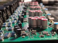
5 samples of Cosmos ADC were soldered by my hands and will be sent for tests.
Regarding compensation technics, no doubt does exist the way to get 9822 THD even better but who really needs that if a simple 90x50mm board being powered from USB, provides a few db better THD+N performance than AP SYS2***?
Regarding compensation technics, no doubt does exist the way to get 9822 THD even better but who really needs that if a simple 90x50mm board being powered from USB, provides a few db better THD+N performance than AP SYS2***?
Attachments
on the ASR forum the guy from Soncoz made some experiments to find that fact and successfully fix the hump.
At the price of SINAD and SNR performance. The Soncoz guy essentially lowered in I/V stage gain and raised the summing gain. The penalty is noise, and a good part of the hump becomes buried in it. As I said above, the lead-lag network in parallel with the I/V resistor does exactly nothing, other than adding some HF noise. That’s because instead of having the gain->0 with frequency, the gain will then asymptotically approach a constant value>0.
I confirmed this on the ES9038PRO too. If the ESS DAC is clocked async at a constant 100MHz, there isn’t a damn thing you could do to completely avoid the hump, without a serious noise penalty. Fortunately, up to 50MHz clock, a combination of I/V bias at about 1/3 AVCC and I/V and summing gain structure allows a good trade between the hump and the added noise. Meaning 384KHz sampling rate, good enough for the consumer market.
P.S. John Yang of Topping fame is right on spot in the same thread. What John is doing extra (concluded after reverse engineering one of his products), I won’t disclose here, it would be unfair. While still not the ultimate cure, it is at least a reproducible and systematic approach to avoid the hump, that works for all ESS DACs. It also comes with probably the least possible noise performance degradation.
Last edited:
I never used 100MHz, I found that 100% impractical, and no idea why all Chinese bords with 9038Q2M use 100MHz clock, mystery..
PS: aah, perhaps the datasheet said "the max clock freq 100MHz" and that point was wrongly translated to putonghua like a recommended clock = 100MHz ))
PS: aah, perhaps the datasheet said "the max clock freq 100MHz" and that point was wrongly translated to putonghua like a recommended clock = 100MHz ))
Last edited:
Not only the Chinese crap boards do, also some commercial DACs from otherwise reputable companies do, I won’t name names here. Somehow, based on the oversampling principles, people think the higher the clock rate, the better the performance. While forgetting or not knowing that the ESS DAC actually works at a fixed x128 rate.
Last edited:
While forgetting or not knowing that the ESS DAC actually works at a fixed x128 rate.
I saw a difference in this mode between Pro and Q2M versions - Q2M has noise floor rising at the high frequencies (noise shaping?).
One problem with the REW multitone test is theat the harmonics land on source tones.
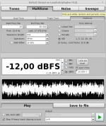
Yes, my test used 1/3 octave spacing (IMO the same as Amir uses in his ASR tests) which is suboptimal here. REW offers a no-interharmonic-distortion sequence Signal Generator :
The tones can be spaced linearly, logarithmically at a selected fractional octave or fractional decade interval or in a sequence that places the tones such that they do not correspond to the low order harmonic or intermodulation products of other tones ('No Interharmonic Distortion' or NID). Octave fraction spacing uses frequencies from the preferred list. In all cases the tones are placed at the bin centres of an FFT of the selected sequence length, so that the behaviour of a system fed by the tones can be observed on an FFT with at least that length using a rectangular window.
Attachments
Then I obviously don't understand your method; as I naively see it, you are providing one set of compensation values (allegedly polynomial coefficients) and then assuming the whole distortion profile over levels and frequencies can be approximated by that polynomial.
I am afraid there is not much you can do with compensating a general signal which changes randomly. For such a signal you have only momentary sample values which can be modified with some correction curve - be it Nth-order polynomial, piecewise Nth-order polynomial, lookup table with linear interpolation between steps, anything. There will always be compromises because the correction curve is static, it does not modify based on the random signal.
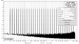
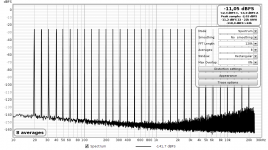
Here is ES9028Pro compensation performance:

And static polynomial compensation performance of my soundcard:
Clearly the very same stuff, no magic involved in any case.
So I wonder if your method mostly corrects the intrinsic DAC multiple distortion sources, or mostly the distortions of the external circuitry (like e.g. layout asymmetries)?
Only digital input and analog output for the generator (and vice versa for the analyzer) are available, no probes inside to separate the DAC chip from its external circuitry. The distortion measurement (and thus the compensation) always covers the whole block. Just like the ESS compensation unless you measure the resultant distortion just at the DAC outputs (highly unlikely). The ESS DAC datasheet (no NDA 🙂 ) says:
THD Compensation can be used to minimize distortion from external PCB components and layout through the generation of inverse second and third harmonic components matching the target system distortion profile.
Of course it compensates also the (very small) internal DAC distortions.
The dynamic compensation I use for single-tones compensates all pre-measured distortions at their level and phase (by generating the same levels and opposite phases), but logically cannot work for a general signal.
Both static samples correction and dynamic generation of "anti-distortions" has been used for many years, nothing new. Internet is full of prior art 🙂
phofman, in their ADC chips entire LUT is available, not just 2nd and 3rd. I hope ESS will do the same for their new DACs.
- Home
- Design & Build
- Equipment & Tools
- ADCs and DACs for audio instrumentation applications