I have not learned to master the IR window stuff in REW, and my room is too bouncy to get anything out of the measurements without this skill.
There isn't much to using the windowing function in REW.
Here is an example, it's the only measurement I have saved of a standard speaker placed in the middle of a room.

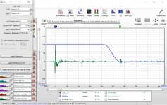
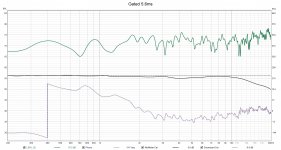
By looking at the impulse response you can see where the first significant reflection is and window the response to cut it at that point. I have chosen 5.6ms in this case. The type of window makes a difference as the shape of the blue curve shows the window.
I've attached some mages below that shows the difference to SPL and phase.
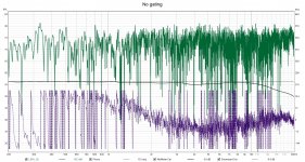
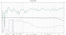
The other option which can be useful for full range in room measurements is to use the Frequency Dependant Window function, where there is a sliding window over time, longer at low frequencies shorter at high. In REW it is measured in cycles or octaves. Cycles means that that many cycles of each frequency are allowed through the gate.
Here is an example, it's the only measurement I have saved of a standard speaker placed in the middle of a room.
By looking at the impulse response you can see where the first significant reflection is and window the response to cut it at that point. I have chosen 5.6ms in this case. The type of window makes a difference as the shape of the blue curve shows the window.
I've attached some mages below that shows the difference to SPL and phase.
The other option which can be useful for full range in room measurements is to use the Frequency Dependant Window function, where there is a sliding window over time, longer at low frequencies shorter at high. In REW it is measured in cycles or octaves. Cycles means that that many cycles of each frequency are allowed through the gate.
Attachments
In the graphs above it is gated out, either by a fixed gate at a set time or a variable gate depending on the frequency (FDW).
You can create a filter for it based on a FDW'd measurement either manually with REW and rephase or automatically with something like DRC-FIR. The raw pcm output from DRC is the same format as a minidsp .bin file all you have to do is change the extension.
The other option to reduce room influence on your measurement is use vector averaging. Where you take multiple measurements at different points in space and use REW's vector average function the room influence will be reduced significantly above the transition region.
If you keep the measurement positions close to each other, within the space of your head, they will not be wildly different but the combined result will be more anechoic in appearance.
More experiments, and more results
I'll try to summerize the situation so far to make this post more complete.
Background
The initial question was: why do I have to adjust the crossover frequencies (i.e. different on Lowpass and Highpass sides) to improve phase alignment?
This is not in the standard theory for LR4 filters.
The short answer was: the crossover frequencies should be equal, and accoring to LR4 theory, all elements should ideally be placed in the same acoustic plane.
If not in the same acoustic plane, the difference shuld be compensated with a delays.
This makes sense, especially since I'm building an active Hypex DSP based speaker. A delay is easy to implement, just change the settings in the GUI.
The problem I have found is that the delay only can be set in steps of ~3.66mm (since Hypex sample frequency is 93.75 kHz).
This is combination that my elements when mounted flush in the baffle not "hit" these steps perfectly caused problems.
In fact the distances instead hit close to the middle between steps, making the problem as bad as it could get.
My initial attempt to compensate for this was to instead adjust the crossover frequencies which lead to a less than optimal result, since the frequency shift has other negative impacts.
This was also the startin point for this thread.
Solution(s)
One solution is to rearrange the relation between the element distances by tilting the speaker slightly backwards.
(This is a standard solution to this kind of problem since long and used in many professional designs)
First I tried with putting 8 mm under the front feets, and this dramatically improved the situation (see post #40).
The problem was that this was perfect for the woofer-mid alignment, but hit again the "middle between steps", i.e. ~1.8mm off, for the mid-tweeter alignment.
Next try after some geometrical calcuations was 4.5mm under front feets which hit the sweetspot for mid-tweeter alignment, but not for woofer-mid alignment.
Fortunally my design with a separate top box makes it possible to move the mid-tweeter section slightly backwards from the woofer and
1-1.5mm is enough to get a close to perfect alignment also for the mid-woofer.
This is the by far best setting and solution I have reach so far.
Compared to where I started with a significant crossover frequency difference between Lowpass and Highpass sides the sound is now much better.
The percieved frequency curve is more flat and the impulse response is improved (no measurements to back this up with though...).
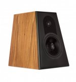
Last but not least the only published picture of the design which might make this text easier to understand:
(see also Hogtalarshoppen - Community | Facebook)
Many thanks to everyone contributing to a better understanding of how to set this up correctly.
I'll try to summerize the situation so far to make this post more complete.
Background
The initial question was: why do I have to adjust the crossover frequencies (i.e. different on Lowpass and Highpass sides) to improve phase alignment?
This is not in the standard theory for LR4 filters.
The short answer was: the crossover frequencies should be equal, and accoring to LR4 theory, all elements should ideally be placed in the same acoustic plane.
If not in the same acoustic plane, the difference shuld be compensated with a delays.
This makes sense, especially since I'm building an active Hypex DSP based speaker. A delay is easy to implement, just change the settings in the GUI.
The problem I have found is that the delay only can be set in steps of ~3.66mm (since Hypex sample frequency is 93.75 kHz).
This is combination that my elements when mounted flush in the baffle not "hit" these steps perfectly caused problems.
In fact the distances instead hit close to the middle between steps, making the problem as bad as it could get.
My initial attempt to compensate for this was to instead adjust the crossover frequencies which lead to a less than optimal result, since the frequency shift has other negative impacts.
This was also the startin point for this thread.
Solution(s)
One solution is to rearrange the relation between the element distances by tilting the speaker slightly backwards.
(This is a standard solution to this kind of problem since long and used in many professional designs)
First I tried with putting 8 mm under the front feets, and this dramatically improved the situation (see post #40).
The problem was that this was perfect for the woofer-mid alignment, but hit again the "middle between steps", i.e. ~1.8mm off, for the mid-tweeter alignment.
Next try after some geometrical calcuations was 4.5mm under front feets which hit the sweetspot for mid-tweeter alignment, but not for woofer-mid alignment.
Fortunally my design with a separate top box makes it possible to move the mid-tweeter section slightly backwards from the woofer and
1-1.5mm is enough to get a close to perfect alignment also for the mid-woofer.
This is the by far best setting and solution I have reach so far.
Compared to where I started with a significant crossover frequency difference between Lowpass and Highpass sides the sound is now much better.
The percieved frequency curve is more flat and the impulse response is improved (no measurements to back this up with though...).
Last but not least the only published picture of the design which might make this text easier to understand:
An externally hosted image should be here but it was not working when we last tested it.
(see also Hogtalarshoppen - Community | Facebook)
Many thanks to everyone contributing to a better understanding of how to set this up correctly.
With unassailable logic, you dismiss the well-known and likely audible consequences of tilting your speaker cab in favour of supporting a notion (audibility of relative phase outside lab testing) that may have no basis in reality.
But as you posted earlier, "...my ears have helped me more than the umik."
B.
But as you posted earlier, "...my ears have helped me more than the umik."
B.
Last edited:
It's an interresting solution, many ditch the LR4 because of the hardening effect and go for the LR2 with an pair invert.
Maybe that angle hit the listener more soft.
It sounds that you are in to this design atm. QLN reference 🙂
Maybe that angle hit the listener more soft.
It sounds that you are in to this design atm. QLN reference 🙂
Attachments
Last edited:
With unassailable logic, you dismiss the well-known and likely audible consequences of tilting your speaker cab in favour of supporting a notion (audibility of relative phase outside lab testing) that may have no basis in reality.
But as you posted earlier, "...my ears have helped me more than the umik."
B.
Sorry, my english is not good enough to understand if your post is ironic or sarcastic 🙁
It has been mentioned a few times in this thread but the underlying assumption when using a LR4 crossover is that you have good phase alignment between the drivers prior to applying the LR4 LPF/HPF. In addition to phase issues caused by physical offset the phase response of the drivers also needs to be considered.
I think you are overstating the impact of the 11 microsecond steps when implementing DSP delay. Assuming you have perfect phase alignment between the drivers other than an 11 microsecond deviation from the ideal delay only results in a 0.04 dB deviation in frequency response and a 5.5 microsecond (half step) deviation only results in a 0.01 dB deviation in frequency response.
It seems more likely that you have phase response variation from the drivers themselves that is more significant than this. As you have not completed gated/near field measurements of the drivers themselves as suggested earlier in this thread it is difficult to understand the issues you are dealing with prior to implementing delay to correct physical offset.
Also, since you are using DSP, it is very easy to adjust the frequency response of each driver to be flat at least one octave above and below the crossover frequency.
This is also very important for the LR crossover in addition to the delays.
To do this you need to perform gated measurements.
This is also very important for the LR crossover in addition to the delays.
To do this you need to perform gated measurements.
Sorry, my english is not good enough to understand if your post is ironic or sarcastic 🙁
On the web, I try never to be sarcastic. My text says exactly what I mean, not backwards sarcasm or exaggerated irony. You cooked-up an elaborate logical argument about phases when the simple explanation is available.
But I am chiding you for boasting your ears are better than mic.
B.
Last edited:
I realize that my measurement skills needs a big leap forward if I should get any further.
Until then my ears will be a better tool to me than my lack of measurement skills.
Many thanks for helping me to get to this point.
Until then my ears will be a better tool to me than my lack of measurement skills.
Many thanks for helping me to get to this point.
Trying to get a crossover right without good measurements is a game of Russian roulette as you have found.
The point is to make it sound good to you so there is no issue with ultimately going with your ears.
Like the other posters I think you have to be careful of mixing issues with their outcomes and without good measurements this is easy to do.
Tilting the speaker changes much more than just the relative delays between the drivers and what it changes is likely much more significant to the sound that a little bit of phase offset.
I would have a look at this guide by Kimmo on how to take measurements for crossover simulation
https://kimmosaunisto.net/Software/VituixCAD/VituixCAD_Measurement_Preparations_REW.pdf
With a recent REW Beta and a UMIK and Acoustic timing references it is very possible to take fully time locked measurements which is what you need to do anything with delay and phase adjustment.
If you don't want to learn VituixCAD for the crossover then you can do a lot in REW with the phase alignment tool. That will show you in real time the effect of any changes.
GDan in #74 said "Also, since you are using DSP, it is very easy to adjust the frequency response of each driver to be flat at least one octave above and below the crossover frequency."
Good luck doing that to the mids on a Unity or Synergy speaker 😀
Good luck doing that to the mids on a Unity or Synergy speaker 😀
The reason processors have delay is because canned filters don't have the versatility to be useful without it. Otherwise, delay isn't strictly a necessary thing to have.and describe what you mean...
This aint gonna work, you need 2-channel measurements. single channel power response optimising takes lots of time, 1001 sweepsWith a recent REW Beta and a UMIK and Acoustic timing references it is very possible to take fully time locked measurements which is what you need to do anything with delay and phase adjustment.
- Home
- Loudspeakers
- Multi-Way
- Active LR4 crossover phase matching using a DSP