Acoustic Timing Reference is the only option with a USB mic you can't do a loopback with a single channel device.
This seems to keep going round and round I don't understand where the confusion is
This seems to keep going round and round I don't understand where the confusion is
Last edited:
Sorry i had crossovers on when i tried so it did not work with me.
Yes it really works and it is accurate
Yes it really works and it is accurate
I think the slow drifting follow both sides perfect so there should not be a better phasing at any spot? (in signal).Depends on what you mean by mitigate...
if you mean at a single freq, yes you can. (But choose the single freq at the expense of all others.)
if you mean through the entire xover range, no you absolutely cannot.
Attachments
It's not that critical though is it when you consider the audibility thresholds?Depends on what you mean by mitigate...
if you mean at a single freq, yes you can. (But choose the single freq at the expense of all others.)
if you mean through the entire xover range, no you absolutely cannot.
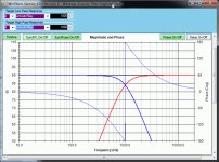
Does the phase not correspond to the magnitude?
What made you think that?
BTW I think talk of synergies has nothing to do with this thread.
No, not really. The mag shift is so abrupt due to the notch reflection, it's not something you can get warm and fuzzy about correcting with EQ, cause no matter what you do, it won't fully go away.
It's a time domain issue that's large enough, it exceeds the minimum phase mag-phase relationship bond that exists in smoother response curves, or so i currently think.
What made me think minimum phase can only come from a single driver, is it's what I've always thought, and remember saying quite a few times.
Simply because the moment multiple driver geometry comes into play, the mag and phase relationship changes with listening/measurement location.
I'm confused; i thought this is pretty commonly accepted. No?
In my mind, the only valid minimum phase EQ's are the ones that hold consistently over the required coverage area needed, both on and off axis.
Maybe multiple driver line arrays are more stable mag vs phase at various locations, when C-to-C spacing is tight enough. But that's away from this thread, (and I agree with your comment re synergies.)
It's not that critical though is it when you consider the audibility thresholds?
I guess that just depends on who/what you read and trust...
...and each of us has to decide that for themselves.
Personally, i don't trust decades old research that didn't have the means to explore audibility thresholds like we do today.
Many of the audibility threshold comments remind me of the early digital photography days, when a lot of people almost fiercely defended the idea that more megapixels had value only if doing big enlargements or tight crops expanded up to normal size.
Their position rested on longstanding Airforce research from 1951 that the human eye could only resolve a little over 200 lines per inch.
Well, as digital cameras and printers kept improving, it wasn't long before it became apparent that 200 LPI was all that could be printed distinctly in 1951, haha.
So yeah, i'd like to see some new and credible audibility threshold tests.
In the meantime, i keep listening and measuring, .....both appear to improve together..... so for me it is fairly critical.
What have you discovered about your audibility threshold, have you found it differs much from the old research findings?
The first link is showing the difference between LR2 and LR4 when there is a directivity mismatch between drivers.
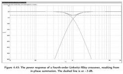
Just to be clear: AFAIK all LR crossovers will have a power response dip at the crossover point. This is from a Rane Audio paper (Linkwitz-Riley Crossovers: A Primer):
"Linkwitz-Riley alignments produce constant voltage response (voltage vectors sum to unity) at the crossover frequency, but they may not produce constant power. At the crossover frequency, each voltage output is half of normal. This produces half the normal current into the loudspeakers. Since power is the product of voltage times current, the power is one-quarter of normal. Considering a simple two-way system, the combined total power at the crossover frequency will be half of normal (one-quarter from each driver), producing a dip of 3 dB at the crossover frequency in the overall power response, provided there is no additional phase shift contributed by the drivers themselves -- such is never the case."
Directivity mismatches can certainly make the dip worse. And I'm not sure why Rane says "may not produce constant power".
Thank you 🙂Here
Power response comparison with Linkwitz-Riley crossovers
And the bottom half of this page
Crossovers: Active crossovers
And a listen test 😎
But is this even a problem it you just dont try to match a big midrange with a small beaming tweeter?
Cause with a waveguide and some proper matching of drivers and cabinet design.... things looks pretty good to me

DXT-MON | 5 ″ 1 ″ | Near field monitor | Compact speaker
I actually bought a set of DXT's and matched them with a 5" at 2kHz on a likewise baffle with LR4 filters - no hard sound here. Smooth clean measurements - smooth clean sound 😎
Viper_user
Do you have a link or a short description of your system, so I can better understand the design you are using?
Do you have a link or a short description of your system, so I can better understand the design you are using?
Atm i run it like this:
TC BMC-2 --> DCX2496 (rca mod) 2 pcs 4-channel amps --> 3-way speakers Wifa/Scan speak (8" 2,6" 1").
TC BMC-2 --> DCX2496 (rca mod) 2 pcs 4-channel amps --> 3-way speakers Wifa/Scan speak (8" 2,6" 1").
I almost bought bmc2 back in days, do you use it digital between dcx? Volume controls spdif on bmc2
manninen, Aha it's a cool unit! I like the flat out button (REF)
Yes i use the digital input, have trimed my amps down so i can run flat out.
Yes i use the digital input, have trimed my amps down so i can run flat out.
Just to be clear: AFAIK all LR crossovers will have a power response dip at the crossover point. This is from a Rane Audio paper (Linkwitz-Riley Crossovers: A Primer):
"Linkwitz-Riley alignments produce constant voltage response (voltage vectors sum to unity) at the crossover frequency, but they may not produce constant power. At the crossover frequency, each voltage output is half of normal. This produces half the normal current into the loudspeakers. Since power is the product of voltage times current, the power is one-quarter of normal. Considering a simple two-way system, the combined total power at the crossover frequency will be half of normal (one-quarter from each driver), producing a dip of 3 dB at the crossover frequency in the overall power response, provided there is no additional phase shift contributed by the drivers themselves -- such is never the case."
Directivity mismatches can certainly make the dip worse. And I'm not sure why Rane says "may not produce constant power".
Thx for that.
No matter how many times i read that Rane Note, i always learn something new.
I wish I could understand understand what Rane is saying about power response dipping.
Can't grasp it yet.
Because it seems to me, Rane is talking amplifier power, not acoustic power, when it says two 1/4 power sources only equal 1/2 power.
It appears to set aside the acoustic gain from increased efficiency of 2 drivers.
I mean take subs with no xover, and essentially omni, so no power mapping/integrating issues:
you can use one sub at 2.83v for 100dB, or two at 1.41v for the same 100dB.
The two subs will need 1/2 the wattage to do acoustically what the one does.
Because we know if voltage is 1/2, that's -6dB SPL from the speaker. And yes, =1/4 power.
But we also know two speakers equally driven sum to +6 dB....
Even if they are both using 1/4 power from their starting reference SPL.
So 1/2 total wattage doesn't mean 1/2 total acoustical power, when moving from one driver to two, both equally driven.
Again, it appears to set aside the acoustic gain from increased efficiency in using 2 drivers.
In my mind, the same logic applies at xover frequency and thru the summation region....the summation principle seems independent of the xover.
What is this poor mellon missing ?
It very much appears Rane is talking about amp power, which doesn't make sense to me. 😕
Thx!
An interference notch can't be corrected by minimum phase EQ, but you have to be careful assuming that it means the effect creating that issue is also non-minimum phase in natureNo, not really. The mag shift is so abrupt due to the notch reflection, it's not something you can get warm and fuzzy about correcting with EQ, cause no matter what you do, it won't fully go away.
It's a time domain issue that's large enough, it exceeds the minimum phase mag-phase relationship bond that exists in smoother response curves, or so i currently think.
Most times it would be true but there can be times when it isn't. Bill Waslo wrote this in another forum and I think it is a good way of describing itWhat made me think minimum phase can only come from a single driver, is it's what I've always thought, and remember saying quite a few times.
Simply because the moment multiple driver geometry comes into play, the mag and phase relationship changes with listening/measurement location.
I'm confused; i thought this is pretty commonly accepted. No?
"For a given fully described frequency response magnitude curve (the "dB" curve), there is only one phase curve (the "degrees" curve) which it can have while still being for a causal system (no time domain results until its cause happens) and with minimum overall time of flight in play".
Yes that is correct, it was the comparison being used for justifying an LR2 sounding better than an LR4 without considering the directivity mismatch that I was trying to point out. LR2 and LR4 both have a 3dB power dip, which will be wider on the LR2.Just to be clear: AFAIK all LR crossovers will have a power response dip at the crossover point.
Douglas Self has some very useful information in "The Design of Active Crossovers" book with graphs that can help explain it. Because the crossover point is at -6dB in an LR there is 3dB power dip. The outputs are uncorrelated and when you RMS sum -6 and -6 you get -2.989.I wish I could understand understand what Rane is saying about power response dipping.
Can't grasp it yet.
What is this poor mellon missing ?
Like this, graph attached below from pg 89
Attachments
Douglas Self has some very useful information in "The Design of Active Crossovers" book with graphs that can help explain it. Because the crossover point is at -6dB in an LR there is 3dB power dip. The outputs are uncorrelated and when you RMS sum -6 and -6 you get -2.989.
Why are the outputs uncorrelated? If the crossover is working correctly they should be perfectly in phase at the crossover frequency. And I also thought that two speakers working at -6dB electrical power each would generate the same sound pressure as one speaker at 0dB electrical power.
There is another quote from the section on first order filters which explains a little more why the outputs are considered to be uncorrelated.
"The power response is shown in Figure 4.3. Since the two contributions to the total power are uncorrelated (because of multiple room reflections and so on), they add in an RMS-fashion; in other words you take the square root of the sum of the squares of the two levels".
If you go to a calculator like this one
Total dB level adding of incoherent or noncoherent uncorrelated sound sources
and go down to the section on adding of two acoustic levels you can see that adding -6dB to -6dB gives -2.89dB.
Isn't it the goal to have the speakers as closely together as possible so they can form a mostly uniform wavefront? How about coaxial speakers in this case - do you think they also emit uncorrelated wavefronts?
According to Fulcrum Acoustics. You just need TQ magic 👌😀
#2 - Temporal Equalization (TQ) - an overview - YouTube
#2 - Temporal Equalization (TQ) - an overview - YouTube
- Home
- Loudspeakers
- Multi-Way
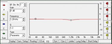
- Active LR4 crossover phase matching using a DSP