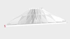
What is horn coloration?
High order modes, Sound wave propagation.
There's certainly no horn coloration whatsoever.
Listening to the g2 520, I agree.
So far it's looking good. I'd like to print a pair myself but don't have a printer big enough... 🙂


Printing it in parts doesn't sound very cool, but perhaps making a mold for casting concrete (or acrylic) would be an option.
Printing it in parts doesn't sound very cool, but perhaps making a mold for casting concrete (or acrylic) would be an option.
Last edited:
Anyway, it's available on Cults.
(STEP file included - this one can be easily scaled for a 1.4" throat, then it will be 590 x 510 mm, this must be enough.)
And now I need a break from designing horns... 🙂
(STEP file included - this one can be easily scaled for a 1.4" throat, then it will be 590 x 510 mm, this must be enough.)
And now I need a break from designing horns... 🙂
I would machine it out of wood 🙂So far it's looking good. I'd like to print a pair myself but don't have a printer big enough... 🙂
View attachment 1466521 View attachment 1466522
Printing it in parts doesn't sound very cool, but perhaps making a mold for casting concrete (or acrylic) would be an option.
I like how you made the lattice structure on the back of the horn. Is there an easy way to do this?
I thought about something like that but finally decided that it's better to make the whole object simply thick enough. What you show is then basically an infill structure, only without the rear shell.

Last edited:
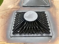
No ist not an infill structur, it‘s plottime and construction for weight (tweeter) optimized. The whole plastic is now only for construction and not for infill, which you cant damp. I have to fit the tweeter from the side of the horn and not from behind the tweeter. With 2cm infill the plottime was about 90hrs. Now 30hrs+ 0,5hr painting. And the resonances are going away fast when I knock on the waveguide.
Last edited:
Wouldn’t this shape be the easiest to glue up clean? especially considering the mouth is also square? This would make clamping for glue ups also easier. Even in terms on align the parts, only very basic alignment pins would be required. Also - given how the peices would lay on the bed and the thickness of the horn, I think the factors lower the risk of delamination and wrapping (for those of us that are working with cheaper printers). Only thing that would need modification is have 4 mounting holes across each edge (so as to avoid necessitating printing a hole at the glue joint).Printing it in parts doesn't sound very cool, but perhaps making a mold for casting concrete (or acrylic) would be an option.
You don't have to cut it exactly in half. But it's something to consider, I may change that.Only thing that would need modification is have 4 mounting holes across each edge (so as to avoid necessitating printing a hole at the glue joint).
BTW, this can be all done in a slicer (the cutting, alignment pins, etc.), which is also what I assume anyone can do.
Last edited:
I'd be reluctant to print anything above ~10 hours 🙂With 2cm infill the plottime was about 90hrs. Now 30hrs+ 0,5hr painting.
Those are all simulations so it's an "ideal" driver, but for the purpose of the polar maps this virtually doesn't make a difference.
I bet it'd get even deader if you were to paint on top of that with two-part epoxy... then again, I'm not sure how well it would stick to that black stuff.This made my 3D Plotter specialist, I only know that he use plasticity for designing.
Yesterday I paintet the horn backsides with bitumen based underbody protection. That‘s very helpful against the resonances of the Material.
View attachment 1466656View attachment 1466657
Those are all simulations so it's an "ideal" driver, but for the purpose of the polar maps this virtually doesn't make a difference.
I see. So any driver would project a convolution of that map.
That program you use is very useful. I’d like to try it and see if I can figure it out.
@mabat I decided to try a constant-directivity WG with 1,4 driver. So I already bought A460D and ESP, I want to combine them.
Am I correct that I can use one of the adapters for the 1“ driver (so, which one?) and connect the ESP to it at the throat level where the throat is 1.4”? If I want to increase the horn slightly (like 10-%) would I still connect the output of the ESP at that throat level where the throat would also be 1.4 inches?
Am I correct that I can use one of the adapters for the 1“ driver (so, which one?) and connect the ESP to it at the throat level where the throat is 1.4”? If I want to increase the horn slightly (like 10-%) would I still connect the output of the ESP at that throat level where the throat would also be 1.4 inches?
Hi All,
I'm new to this process, though been reading through the thread as much as possible. I recently started printing the 460G2, thinking it would match the Rosso 65CDN-T well. When I print though, the 'base' has a ~2" opening. Do I need an adapter to pair this CD, & if so which one?
I'm new to this process, though been reading through the thread as much as possible. I recently started printing the 460G2, thinking it would match the Rosso 65CDN-T well. When I print though, the 'base' has a ~2" opening. Do I need an adapter to pair this CD, & if so which one?
- Home
- Loudspeakers
- Multi-Way
- Acoustic Horn Design – The Easy Way (Ath4)


