Could this be a part of the secret sauce in Gunnes Focusing? Along with compensation of anomalies in the CD etc. Dave Gunnes is a legend i sound reinforcement.
https://www.fulcrum-acoustic.com/genius2-david-gunness-and-gunness-focusing-15/
EAW owns the rights of the Gunnes Focusing brand but Dave Gunnes has refined (?) the process at his own company Fulcrum Acoustics.
https://www.fulcrum-acoustic.com/audio-technology-insights-resources/temporal-equalization-tq/
EAW owns the rights of the Gunnes Focusing brand but Dave Gunnes has refined (?) the process at his own company Fulcrum Acoustics.
https://www.fulcrum-acoustic.com/audio-technology-insights-resources/temporal-equalization-tq/
Last edited:
You can't "precondition" anything that you don't have any control of. Reflected sound in a room is such a thing, IMO.
The only thing that can be done about this is to try to eliminate it. We need a one-way acoustic medium 🙂
The only thing that can be done about this is to try to eliminate it. We need a one-way acoustic medium 🙂
Last edited:
A460D + B&C DH450:


The same driver in A400G2 with a long(ish) adapter:


The same driver in A400G2 with a long(ish) adapter:
Last edited:
Can you show the frequency response? Now the question is: is the increased mid-range impedance that makes the pressurized room effect the driver a result of the extensions, or does it depend on some other factors like the driver build or radiation pattern? We would probably like to avoid such a high impedance that it acts upon the driver and mess up its response. A dome tweeter would not have this issue. And does it increase distortion?
Questions I don't have answers for.
- I'm thinking about putting a mic probe in the wall of the throat. It should be possible to get an impulse response, provided the dynamic range will suffice. That way we could better quantify the effect, perhaps.
- I'm thinking about putting a mic probe in the wall of the throat. It should be possible to get an impulse response, provided the dynamic range will suffice. That way we could better quantify the effect, perhaps.
Last edited:
Here's a relevant post quoting an old post (from 2001) by Dave Rat of Rat Sound.On the Synergy horns Tom Danley used a small inductor in parallel to the compression driver to "stiffen" them up.
Impedance measurements are used to measure enclosure resonances as I've learned in my journey: https://www.diyaudio.com/community/threads/efficient-2-way.380822/page-12#post-7231927
The cushion test of yours makes me think about some comb effect: larger frequency differences with smaller spaces. The fact that is is quite stable under rotation of the waveguide makes me think otherwise.
As the waveguide+CD is largely a linear system, signals can simply superimpose. This means that you measure CD+waveguide, reflections of its own sound, but also other sound (e.g. your 1 and 1.5kHz phone sounds) when determining the impedance. The wandering/wildly varying amplitude of the peak when you play a sound with your smartphone might be caused by a random phase difference between your test signal and the tone from your phone. Why one is varying slowly and the other wildly.... I can't explain that.
Wild idea... Is there any (stable) 'noise' source in your measurement room?
I'd like to understand how that doesn't give a phase shift detrimental to the design goal of the 'Synergy' horn.On the Synergy horns Tom Danley used a small inductor in parallel to the compression driver to "stiffen" them up.
Going usual 2nd order, cap / inductor certainly would if I introduced and measured it.
Was the inductor a VERY low value? This not 2nd order effect?
I guess it's part of the "no named crossover" implementation🙂
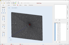
Sorry for the late reply. I was a little bit busy today.Did you try to replace your msh file with the one I generated? I mean the file ath.msh in your ABEC project directory.
And did you try to open directly the project I generated?
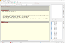
I reinstalled ABEC3 today and then again tried to open your project file. The project file can be opened without an error message. However, starting the boundary element solver leads to a situation where the solver runs for about 15 minutes and then stays at 24% progress.
Furthermore, there are some abnormalities in the observation script, see attachment.
Kind regards
Klaus
Attachments
OK, now you really need a newer ABEC. You can use the Pro version - without a release code it will basically behave like the demo. The links are still working: http://www.randteam.de/_Software/ABEC3_Pro/Download-ABEC-Pro.html
- As for the processing time, always check the number of mesh elements and try to keep it low, say below 5000 on a regular PC. With a 3D mesh, it's always a tough balance between the computation time and the accuracy/reliability of the result and its upper frequency limit. This is a lot easier with the axial symmetry, where it's much faster.
- As for the processing time, always check the number of mesh elements and try to keep it low, say below 5000 on a regular PC. With a 3D mesh, it's always a tough balance between the computation time and the accuracy/reliability of the result and its upper frequency limit. This is a lot easier with the axial symmetry, where it's much faster.
Last edited:
Thanks for the download link - now everything seems to work with the ABAC project you created (beside the long computation time). 🥳
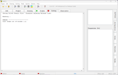
However, when I open the ABAC project (that was created by myself), the same error message "List index out of bounds (-1)" occurs. I used the definition file you provided a few posts earlier... It feels like only one more small step is necessary to get everything working properly. 🙂
However, when I open the ABAC project (that was created by myself), the same error message "List index out of bounds (-1)" occurs. I used the definition file you provided a few posts earlier... It feels like only one more small step is necessary to get everything working properly. 🙂
Attachments
Any suggestions what to do? I am already using gmsh 4.6.0.. Any old or corrupted config files that may cause the problem?
I think I've had similar problem and I solved it:Any suggestions what to do? I am already using gmsh 4.6.0.. Any old or corrupted config files that may cause the problem?
I downloaded the latest gmsh version and then I opened it and choose Help -> Restore all options to default
Maybe try restoring on 4.6.0 and if it will not work try newest.
Let's return to the sunburn hypothesis for a bit. Your measurements affirmed the assumption that the small wiggles that showed up in the 460 measurements are room dependent and directional, hence reflected sound. I have not seen an impedance measurement of the sunburned 520, but from its frequency response, it must suppress the room reflections somewhat better. A question that would help is why the difference. So the second factor is the driver impedance. Seemingly, acoustic impedance of the horn and electric impedance form a system, and together create the condition that the compression driver is going microphonic, within the bandwidth of a high midrange impedance. Let's assume there is some electro-acoustic causes why mostly in the frequencies between 1-3 kHz this becomes a significant issue, where in the high frequencies the acoustic field is simply changing to quickly, and in the lows, maybe some electronic filter is happening. I any case, when looking at you impedance plots, what we see are peaks between 1.4 to 2 kHz depending on driver-horn combos and effective disturbances maybe between 1 kHz to 4 kHz. Maybe it would now help to take a look at the horn from this frequencies. 1 kHz translates to a section of the horn where its radius is 17.15 cm, or its diameter 34.3 cm, 1.4 kHz translates into a section that is at 12.25 cm radius/24.5 cm diameter, and so on ... Is the microphony that is enabled by the driver impedance, but amplified by acoustic impedance, a structural feature of the waveguide and can it be localized? In fact, the epoxy coating of the 460 reduced the wiggles ever so slightly, but even more, the added mass or acoustic absorption of the blanket over the adapter/driver, shielding the backside of the waveguide from reflected sound power, did even more so. Maybe the sunburn of the 520 changed its structural integrity in such a way that the 'receptive' areas of the waveguide were 'mistunes' and could not resonates and transmit the reflected sound in a manner a properly printed device does.- It can still be the body of the horn resonating. Tapping on the horn during the measurement has a similar effect, although one has to be tapping quite a lot to see the additional effect on the impedance curve. But it also can be the sound of the tapping...
- Home
- Loudspeakers
- Multi-Way
- Acoustic Horn Design – The Easy Way (Ath4)


