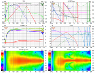
Important thing is to keep the pattern of the waveguide similar to the woofers and you can crossover anywhere below frequency the woofer response gets too narrow, and of course higher than the compression driver is capable to.
Just this: I don't think this is correct. There is several goals with pattern width in a two-way, which is coverage angle for itself, sloping of DI through sound power and a smooth transition at crossover frequency. What the latter is must be defined: reference axis, listening window, early reflections, power or DI? Here, the magnitude of increasing sound power due to widening pattern width and the magnitude of sound power reduced through interference cancellations have to be balanced. A perfect matching pattern width at crossover frequency might very well lead to issues due to a lack of energy, that was removed through cancellation.
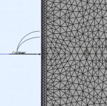
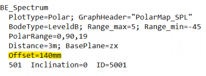
Thank you for the note on rotational axis. I do not know how to set this, can it be done in observations.txt? Anyway, further investigations will be much more reliable after the next release.
Yeah good thinkin, please post when you have examples for this. I'm curious what you have in mind? I think adjusting c-c does it, interference nulls get smaller in comparison to lobes, less cancelled power. Perhaps wait for next release to get more accurately into it with the sims if you wanna get further.
Thought experiment: destructive (and constructive) interference happens to various directions as two non coincident signals interfere and to reduce this either of the sounds need to be attenuated (and quite a lot). Basically this means using higher order filters and/or tighter pattern for the other. Tighter pattern could be done by using big (and deep) waveguide and small woofer, or the other way around perhaps array of woofers with relatively small waveguide, but it also means using narrower pattern for the other that there is going to be kink in the power unless perhaps very gradual slopes, which is opposite what we'd want.
So perhaps only option is to use high order crossover? And of course adjusting the c-c where coincident would be ideal but we can get quite smooth with higher c-c as well, although main lobe is now quite narrow and nulls might point to first reflections depending on the listening setup in a room.
Not sure how it turns out as the system needs to fit together physically as well, simulations would be great to reason further. Maybe keep the waveguide pattern bit narrower than the woofer, then perhaps the "more power" on the woofer compensates some loss in interference which is now bit less as "less sound to sides" with narrower pattern waveguide, c-c adjust the rest. One could have a waveguide whose pattern is similar to woofers at xo but narrower below. Not sure how much there is difference here, perhaps the shape of the graphs change a bit.
Perhaps there is knowledge on this, I just don't know it and trying to reason my way through 😀
Last edited:
One could have narrow vertical pattern for both the woofer and the waveguide, which would then reduce the influence of the vertical lobing to system power response even though the destructive interference would be the same relatively (as in comparison if both had wide dispersion). This would also reduce vertical reflections. Hello to woofer arrays, or just MTM configuration.Maybe keep the waveguide pattern bit narrower than the woofer, then perhaps the "more power" on the woofer compensates some loss in interference which is now bit less as "less sound to sides" with narrower pattern waveguide, c-c adjust the rest.
I think I posted this earlier already but here again. With passive cardioid mid in MTM configuration, flat DI to very low frequency, but it is due to wider than tweeter hotizontal and narrower than tweeter vertical dispersion of the mid. Not sure if this sounds better, plan to try in the summer.

Last edited:
What is the correction step?
0.9873 = propagation path correction [m] (in this case 1m - 1/2")
There’s an example of using PEQ to create non-standard filter orders to reduce directivity error in the acoustic crossover region here:So perhaps only option is to use high order crossover? And of course adjusting the c-c where coincident would be ideal but we can get quite smooth with higher c-c as well, although main lobe is now quite narrow and nulls might point to first reflections depending on the listening setup in a room.
http://excelsior-audio.com/Publicat...tivity_Through_the_Crossover_Region_rev10.pdf
What is the practical size limit for a free standing horn for a 1.4" driver? I kind of feel brave enough to build one with layered OSB construction with around 60 cm diameter (and compare it to the ES radial horn being built).
As I'm in the possession of the 260 (30 deg exit) I have to ask for your guidance in CD choice...
Which of these would you go for?
//
Which of these would you go for?
- 18sound NSD195ND
- Faital HF108(or +R)
- MBS 5530ND (almost = 4550)
//
I will be more specific🙂 BC DE82 or Beyma CP755Ti in home HiFi application. I think there is a point where making the horn larger will not help anything, since one hits the limits of the driver.
what have you got against the 4550? That sounds great and plays lower than most if not all 1" exits. 30 deg exit isn't optimal for it thoughAs I'm in the possession of the 260 (30 deg exit) I have to ask for your guidance in CD choice...
Which of these would you go for?
- 18sound NSD195ND
- Faital HF108(or +R)
- MBS 5530ND (almost = 4550)
//
Eee nothing really - thanks! 🙂
Exit angel(le)s:
NSD1095N = 27°
MBS 5530 = 24
MBS 4550 = 14
Faital HF108 = 31
//
Exit angel(le)s:
NSD1095N = 27°
MBS 5530 = 24
MBS 4550 = 14
Faital HF108 = 31
//
Last edited:
I have been doing that for at least 25 years.There’s an example of using PEQ to create non-standard filter orders to reduce directivity error in the acoustic crossover region here:
http://excelsior-audio.com/Publicat...tivity_Through_the_Crossover_Region_rev10.pdf
But what is he actually doing? I cannot read a literal description of the changes anywhere in the document. It looks like asymmetric slopes (let them be caused by PEQ), from the tilt in the vertical directivity plot between the nulls. Or is there more to it? Also, shifting the phase by delay can help to balance summation off-axis.
The idea is just to use all available degrees of freedom and not stick to some limited set with names like LR, Bessel, etc. My speakers have 1st order HP and third order LP, but with several PEQ bands in and near the crossover points so they don't look like anything with a name. It's all in the software.
Ath 4.8.3b2
Now you can try to export the polars: https://at-horns.eu/release/ath-4.8.3-beta2.zip
1) solve it (needed only once)
2) set only one source active in the file observation.txt (set Weight=0 or 1 for the DrvGroup)
3) calculate spectra and save the data
4) run ath with -r and a tag of the active source (e.g. ath -r woofer), this will export the polars into a subdir "...\Results\FRD"
5) set the other source active in observation.txt
6) repeat steps 3 and 4 for the other source

Here's a sample script. Note that the polars are normalized, including the phases - I haven't thought about that in depth, maybe that's not correct for more than one source, it's up to you to figure out. I can't think anymore today...
You have to set an explicit distance for the polars if you want to export them. This will be also the default delay compensation (which you can manually adjust with the PhaseComp value, that will be added to the Distance value).
Now you can try to export the polars: https://at-horns.eu/release/ath-4.8.3-beta2.zip
1) solve it (needed only once)
2) set only one source active in the file observation.txt (set Weight=0 or 1 for the DrvGroup)
3) calculate spectra and save the data
4) run ath with -r and a tag of the active source (e.g. ath -r woofer), this will export the polars into a subdir "...\Results\FRD"
5) set the other source active in observation.txt
6) repeat steps 3 and 4 for the other source
Here's a sample script. Note that the polars are normalized, including the phases - I haven't thought about that in depth, maybe that's not correct for more than one source, it's up to you to figure out. I can't think anymore today...
You have to set an explicit distance for the polars if you want to export them. This will be also the default delay compensation (which you can manually adjust with the PhaseComp value, that will be added to the Distance value).
Code:
; Enclosure test

Throat.Diameter = 25.4
Throat.Angle = 10
Coverage.Angle = 45
Length = 60
Term.s = 1
Term.n = 4
OS.k = 1.0
Term.q = 0.98

Mesh.Enclosure = {
  Spacing = 30,30,30,200
  Depth = 200
  EdgeRadius = 20
  EdgeType = 1
  FrontResolution = 8,8,16,16
  BackResolution = 20,20,20,20

  LFSource.Below = {
    Spacing = 10
    Radius = 75
    DrivingWeight = 1
  }
}

Mesh.VerticalOffset = 80

Mesh.Quadrants = 14        ; 1/2 symmetry

Mesh.LengthSegments = 24
Mesh.AngularSegments = 64
Mesh.ThroatResolution = 5
Mesh.MouthResolution = 8.0
Mesh.SubdomainSlices =

Mesh.ZMapPoints = 0.5,0.2,0.5,0.8

ABEC.SimType = 2            ; free space
ABEC.MeshFrequency = 1000
ABEC.NumFrequencies = 24
ABEC.f1 = 300
ABEC.f2 = 10000

ABEC.Polars:SPL_H = {
  MapAngleRange = 0,90,10
  NormAngle = 0
  Distance = 2.0

  FRDExport = {
    NamePrefix = hor
    PhaseComp = -2.0     ;[m]
  }
}

ABEC.Polars:SPL_V = {
  MapAngleRange = -90,90,19
  NormAngle = 0
  Inclination = 90
  Distance = 2.0

  FRDExport = {
    NamePrefix = ver
    PhaseComp = -2.0      ;[m]
  }
}

Output.ABECProject = 1
Output.STL = 0
Last edited:
- Home
- Loudspeakers
- Multi-Way
- Acoustic Horn Design – The Easy Way (Ath4)

