Thanks but I believe it will be far more easier for me at the moment to utilize the existing mechanisms included in ABEC. I'd like to learn to actually use the T-matrices some day, as I gathered it is a very powerfull technique.
Here's my attempt at an extremely simple compression driver model (1 inch exit):
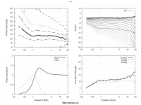
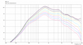
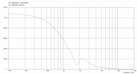
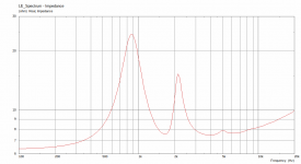
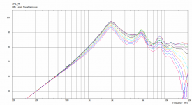
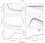
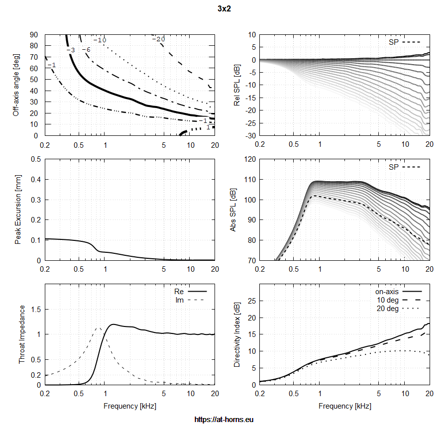
I don't really know what I'm doing and most of the parameters were wild guesses, but it seems to give sane results. It's based on the "Horn Expo 400" example included with ABEC3. First three images are the bare driver in free space and the next three are with the waveguide in this post.
The driving voltage is 2.83V and the measurement distance is 3m (add 9.5dB to get the 1m equivalent).
Code:
Def_Driving
Value=2.83 IsRms
Def_Driver 'Drv1'
dD=44mm
Mms=1.0g
Cms=25e-6m/N
Rms=3.5Ns/m
Bl=8.0Tm
Re=6.3ohm
fre=35kHz ExpoRe=1
Le=0.1mH ExpoLe=0.618
System 'S1'
Driver 'D1' Def='Drv1' Node=1=0=10=20
// Rear enclosure
Enclosure 'Eb' Node=20
Vb=50cm3
Qb/fo=0.1
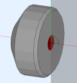
// Phase plug (simplification)
Waveguide 'W1' Node=10=300
STh=3cm2 dMo=20mm Len=22mm Conical
// Conical section between phase plug and exit
Waveguide 'W2' Node=300=400
dTh=20mm dMo=25.4mm Len=22mm Conical
RadImp 'Throat' Node=400 DrvGroup=1001I don't really know what I'm doing and most of the parameters were wild guesses, but it seems to give sane results. It's based on the "Horn Expo 400" example included with ABEC3. First three images are the bare driver in free space and the next three are with the waveguide in this post.
The driving voltage is 2.83V and the measurement distance is 3m (add 9.5dB to get the 1m equivalent).
Attachments
Last edited:
That's just perfect! I think we don't need more at the moment.
Very nice. So the compression ratio is simply expressed as the mismatch between Drv1.dD and W1.STh? That would be very elegant.
BTW, the Waveguide 'W2' could be already easily moved to BEM side, so to fully simulate the conical exit section of the driver as a part of the waveguide.
Very nice. So the compression ratio is simply expressed as the mismatch between Drv1.dD and W1.STh? That would be very elegant.
BTW, the Waveguide 'W2' could be already easily moved to BEM side, so to fully simulate the conical exit section of the driver as a part of the waveguide.
Last edited:
So the compression ratio is simply expressed as the mismatch between Drv1.dD and W1.STh? That would be very elegant.
I'm fairly certain that is the case. So in my example, the compression ratio is about 5. Anyone know what typical values are? I did some searching but couldn't find much so I just took a guess.

If one happen to be in control of the imaginary part of the WG impedance, could it be set so to null it out visavi the driver in order to make it purely resistive on "system" level?
//
//

It seems that an arbitraty filter (EQ) can be added to the source. From the results I could try to insert an EQ making both flat (in acoustic power response or a listening window SPL).
- Any other ideas what might be interesting to see?
- Any other ideas what might be interesting to see?
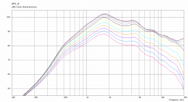
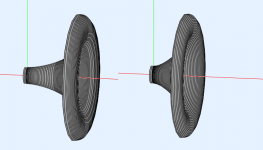
The high loading version on axis FR shape looks exactly like my DE500 in an ES-800 horn by Joseph Crowe. I wanted to compare it with the 10" waveguide, but my second print of the waveguide failed (it is soft and brittle due to partially clogged nozle🙁 ) and I need to make a new one.
Attachments
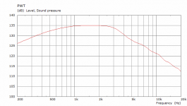
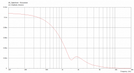
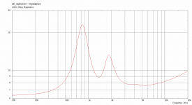
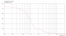
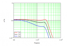
The one thing that seems missing in the CD model is the air gap between the diaphragm and the phase plug. This gap forms a volume that attenuates the response at HFs. I don't see where this effect is in the model. If the gap is very small then this effect is pushed out-of-band, but larger and it has a substantial effect.
The plot below shows this effect on the volume velocity for some rather large gaps - on a PWT.
The plot below shows this effect on the volume velocity for some rather large gaps - on a PWT.
Attachments
There are obviously a lot of things missing. I'm only not sure I see a point in adding them all. If it can be pushed out-of-band, why not just assume so? Here we design waveguides after all, not drivers...
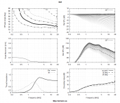
"High" loading:
Is this supposed to be the whole magic? 🙂
Looks promising.
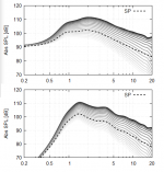
John Sheerin compared a LeCleac'h horn to an unterminated conical horn (without a mouth flair) in ANSYS.
- Home
- Loudspeakers
- Multi-Way
- Acoustic Horn Design – The Easy Way (Ath4)