Here's an updated script. I think the parameters are slightly more accurate this time. It also includes the front volume that Dr. Geddes mentioned 🙂.
Code:
Def_Driving
  Value=2.83 IsRms

Def_Driver 'Drv1'
  dD=44mm
  Mms=0.8g
  Cms=30e-6m/N
  Rms=3.0Ns/m
  Bl=7.5Tm
  Re=6.3ohm
  fre=35kHz ExpoRe=1
  Le=0.1mH ExpoLe=0.618

System 'S1'
  Driver 'D1' Def='Drv1' Node=1=0=10=20

  // Rear volume
  Enclosure 'Eb' Node=20
    Vb=50cm3 Qb/fo=0.1

  // Front volume
  Duct 'D1' Node=10=200
    dD=44mm Len=0.5mm

  // Phase plug (simplification)
  Waveguide 'W1' Node=200=300
    STh=1.52cm2 dMo=20mm Len=22mm Conical

  // Conical section between phase plug and exit
  Waveguide 'W2' Node=300=400
    dTh=20mm dMo=25.4mm Len=22mm Conical

  RadImp 'Throat' Node=400 DrvGroup=1001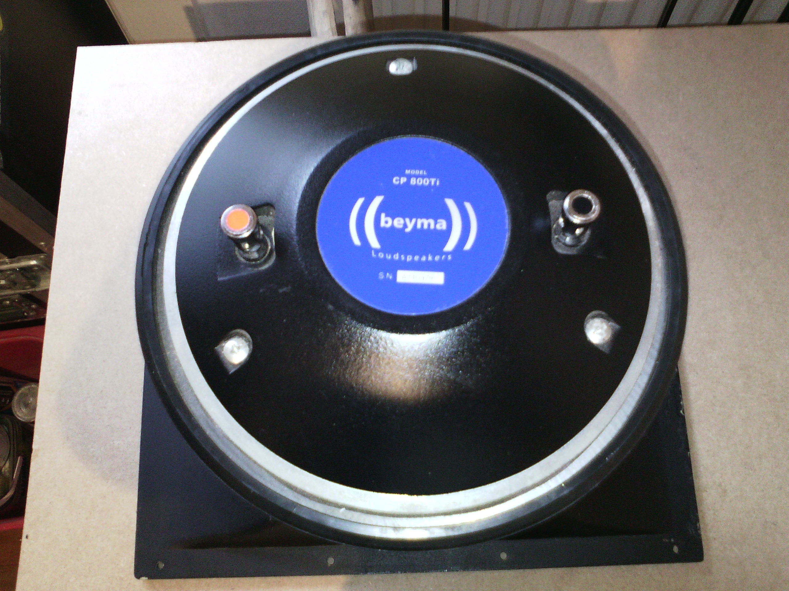
The paper in post #4520 is based on this compression driver:
Please do resize the pictures before posting. 😱
I should point out that I did an AES paper back in the 80's on modeling compression drivers. It was while doing that paper that I realized that we could not calculate the polar response using horns based on Webster's approach. That's when I found the waveguide solution approach which led to the OS waveguides (and more.) It might be useful here as well.
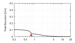
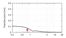
What I would like to know is what's the final measurable quantity that could be thought of as a limiting factor of the lowest usable frequency of a compression driver. Is it the excursion and an onset of higher order distortion? Where would be the limit and based on what? How do we ascertain what's this limit in practice?
BTW, do we have all the data to calculate the total efficiency of the system by now? It seems so.
What I would like to know is what's the final measurable quantity that could be thought of as a limiting factor of the lowest usable frequency of a compression driver. Is it the excursion and an onset of higher order distortion? Where would be the limit and based on what? How do we ascertain what's this limit in practice?
It's going to be excursion, just like any transducer. Larger excursions usually require a degradation of HF response. So it becomes a tradeoff and you have to have some analysis tools to sort out where they are optimum for a given application.
This is precisely the job I just did for a client. So I can answer all your questions and show you plots, but I can't release the code because it's not really mine to give.
I should point out that I did an AES paper back in the 80's on modeling compression drivers ... It might be useful here as well.
This one, I presume?
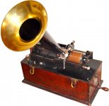
Not exactly state-of-the-art, that one... I wonder how these things measure:

Even in the 1800s they knew better...
Attachments
So I can answer all your questions
I have a few if you don't mind:
1. What are typical values for Mmd and Bl for a 1 inch CD like the DE250 and/or DE500?
2. What's the distance between the diaphragm and phase plug for the above drivers? I used 0.5mm in my (extremely) simplified model. 1mm seems to roll off the highs too much.
3. What is the compression ratio in the above drivers? Mabat suggested 8-10.
As the preferred crossover is around, ideally below 1000 Hz, here's a (hypothetical) catch:
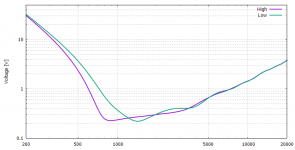
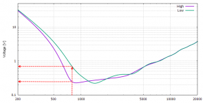
1. Required voltage @ 800Hz for the horns with low vs. high loading.
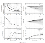
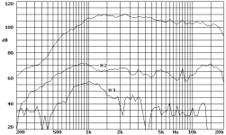
2. On axis frequency response + distortion of a Beyma CP380/M, measured coupled to a Beyma TD250 horn (cutoff: 800Hz) in anechoic chamber, 1w @ 1m.
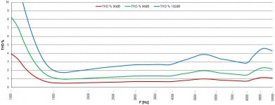
3. Distortion of a SICA CD120.44/640 POLY-8 coupled to a SICA Q07030A short (80 mm) 80° round horn (cutoff: 2000Hz).
1. Required voltage @ 800Hz for the horns with low vs. high loading.
2. On axis frequency response + distortion of a Beyma CP380/M, measured coupled to a Beyma TD250 horn (cutoff: 800Hz) in anechoic chamber, 1w @ 1m.
3. Distortion of a SICA CD120.44/640 POLY-8 coupled to a SICA Q07030A short (80 mm) 80° round horn (cutoff: 2000Hz).
Attachments
Last edited:
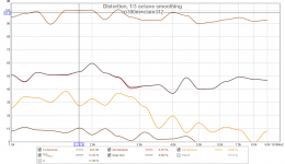
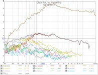
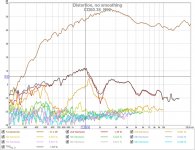
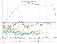
To put things in perspective: distortion obviously differs per driver, as shown by these measurements (by Pet007) of the Celestion CDX1-1745, Sica CD60.38/N92 and B&C DE250 with the STH12 horn, the predecessor of ATH4.
Attachments
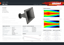
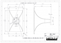
The Beyma CP380/M coupled to a Ciare PR312 (600 Hz) Exponential horn.
just couple notes:
These measurements are mine. SPL level is calibrated, the distance is 1m. These measurements were made using stepped sine technique (in REW) in conventional non-damped listening room to evaluate THD level.
Please correct me if I'm wrong:BTW, do we have all the data to calculate the total efficiency of the system by now? It seems so.
sound_power = area * pressure^2 / (rho * c) * cos(θ)
Where θ is "the angle between the direction of propagation of the sound and the normal to the surface".
Can we put cos(θ) = 1 for a large enough spherical surface around the source?
Last edited:
- Home
- Loudspeakers
- Multi-Way
- Acoustic Horn Design – The Easy Way (Ath4)