I have plenty of those 🙂 That would be great. Attached are some designs (full ABEC projects) I would be especially interested in -It would be interesting to compare DI of square "AthABECDemo" with any version of pure axisymmetric OS horn. If you have ABEC3 project of axisymmetric OS, you can upload it I will calculate "full sphere" DI.
Attachments
Last edited:
I'm compelled to say that, whilst we are way off topic here, I am simply dazzled by the wonderful contributions all are making here and the plentiful facts presented to both substantiate the claims and illuminate the novice, like me!
Thanks to all!
Mabat - more jewel like waveguide images and polars please!
Cheers
Thanks to all!
Mabat - more jewel like waveguide images and polars please!
Cheers
The curved baffle is undoubtedly effective and the final design probably required quite a few simulation hours.
I'm not 100% certain, but I *think* that a baffle that progressively curves backwards produces a polar response that's similar to a horn.
In a horn, we get a beamwidth that gets progressively wider because the angle of the walls gets progressively wider.
A baffle that's curved does something similar I think. As the wavelengths get longer and longer, they're radiating into a beamwidth that's wider and wider.
The downside to a baffle that's curved backwards is that you're throwing away efficiency. The LS50 is kinda infamous for being strained at midbass and low frequencies.
I'm not sure I would put it that way. I would say that the beamwidth gets wider as the wavelength gets longer so the waveguide itself cannot affect it anymore. It is the same for the baffle (or a box for that matter).In a horn, we get a beamwidth that gets progressively wider because the angle of the walls gets progressively wider.
BTW, the mentioned KEF doesn't look like a particularly controlled directivity design to me...
The real effect cannot be determined without a sharp-edged comparison cab, true.
However, basic acoustics implies that towards the low end of the spectrum the wavelengths won't even 'see' the roundovers of your cabs (1000 Hz = 13.56 Inches).
True, not much high frequency energy makes it to the edges. There may still be some measurable effect far off axis though since the direct sound would be highly attenuated and the diffracted energy would not be. I doubt the difference would be audible, however. The roundovers just seemed like Good Engineering™ 😀.
BTW, the mentioned KEF doesn't look like a particularly controlled directivity design to me...
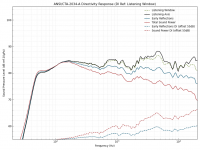
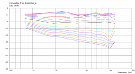
Here's some more data on the LS50 (from audiosciencereview.com, but graphed by me 'cause I think my graphs look nicer 😉). Personally, I think Kef could've done better.
Attachments

Last edited:
I'm not sure I would put it that way. I would say that the beamwidth gets wider as the wavelength gets longer so the waveguide itself cannot affect it anymore. It is the same for the baffle (or a box for that matter).
BTW, the mentioned KEF doesn't look like a particularly controlled directivity design to me...


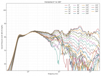
Here's the LS50 and it's vertical and horizontal polars


Here's the Gedlee Nathan and it's vertical and horizontal polars
The Kef isn't perfect, but it's good. And it's also small, affordable, and it's radiation is largely symmetrical. Not the greatest speaker in the world, but for the money it's pretty great.
I think a challenge with a two-way waveguide speaker, like the Gedlee Nathan, is that it's hard to get the vertical polars to be well behaved, due to the center-to-center distance.
Data courtesy of Princeton University : Index of /3D3A/Directivity
Thanks. Your graphs may well be the best looking I have ever seen.Here's some more data on the LS50 (from audiosciencereview.com, but graphed by me 'cause I think my graphs look nicer 😉). Personally, I think Kef could've done better.
OK, but these are normalized to 0 deg, which, as you know, is not always the right thing to do. It's actually extremely misleading in this cases.Here's the Gedlee Nathan and it's vertical and horizontal polars ...
I don't like it. 🙂The Kef isn't perfect, but it's good.
Bateman, your analysis regarding the LS50 makes sense and also (at least partly) corresponds to the published objectives by KEF.
This time I leave my opinion about the loudspeaker aside.
This time I leave my opinion about the loudspeaker aside.
Last edited:
Here's some more data on the LS50 (from audiosciencereview.com, but graphed by me 'cause I think my graphs look nicer 😉). Personally, I think Kef could've done better.
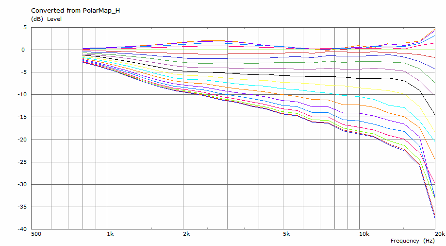
Interesting that the LS50 vertical polars are much better behaved than the horizontal:
Looks like the speaker would perform better if owners flipped it on it's side.
Interesting that the LS50 vertical polars are much better behaved than the horizontal
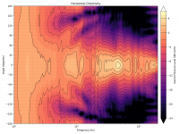
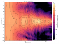
Eh, I don't know if the vertical is much better behaved. There's less of a diffraction artifact (curved feature 700Hz-2kHz, 60°-140°), probably because of the baffle curvature. I've attached the same data, presented with a perceptually uniform color map.
Attachments
The roundovers just seemed like Good Engineering™ 😀.
At least they won't hurt 😉
Talking about loudspeakers, these are coming soon 🙂
It's an all-passive three-way with 1,4" CD, 12" midrange and 15" woofer inside a 4th order band-pass (that's the port under the midrange). Initially there was supposed to be a passive radiator but there's no off-the-shelf suitable - it would be too much effort.
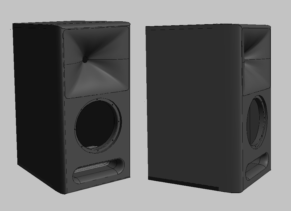
It's an all-passive three-way with 1,4" CD, 12" midrange and 15" woofer inside a 4th order band-pass (that's the port under the midrange). Initially there was supposed to be a passive radiator but there's no off-the-shelf suitable - it would be too much effort.
Attachments
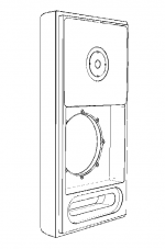

I assume that's the speaker that this waveguide is being used in. I'd be interested in seeing measurements when they're available 🙂.
Sorry, I would rather not discuss construction details here as this is way off-topic. Once these are finished I can share some info in a separate thread maybe.
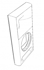
So, I have my first free-standing simulation ever 🙂 I took the 12" demo OSWG.
Infinite baffle:
Free-standing with 5 mm wall thickness (nothing but the waveguide):
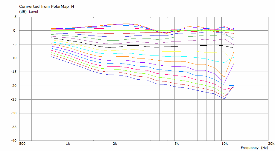
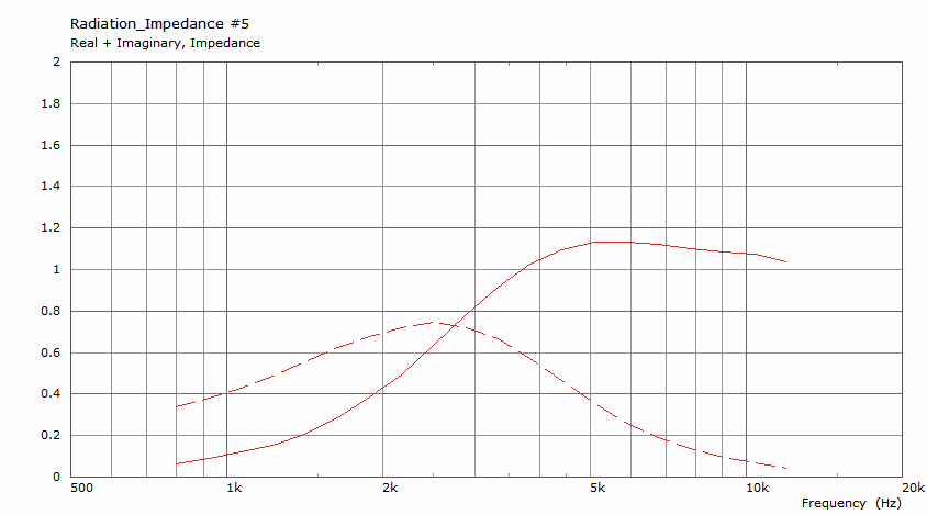
Acoustic impedance of the free-standing one:
(And no, I haven't mixed that up, this is the free-standing waveguide.)
Infinite baffle:
Free-standing with 5 mm wall thickness (nothing but the waveguide):
Acoustic impedance of the free-standing one:
(And no, I haven't mixed that up, this is the free-standing waveguide.)
Attachments
Last edited:
- Home
- Loudspeakers
- Multi-Way
- Acoustic Horn Design – The Easy Way (Ath4)