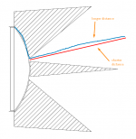
Well, the further parts of the diaphragm will be out of phase with the center since the sound has further to travel. You'll get cancellation as wavelengths get shorter and more out of phase.As for this experiment with the convex side of the diaphragm, my whole reasoning was that it must be easier to get a spherical wavefront from that side than from the concave one (via phase plug and OS throat). I think I will at least give it a try in the simulator to see what I can get. Just in case someone wrote that it's completely silly and why, I would save some effort.
The BMS4550 ring radiator compression driver has a conical throat. Being a ring radiator, there is no radiation from the center to be out of phase with and the driver is reputed to produce a spherical wave front.
454Casull
Sorry, I don't follow.
Sorry, I don't follow.
Would be nice to have it measured. That reminds me that a PWT for this is waiting to be "calibrated".nc535 said:...and the driver is reputed to produce a spherical wave front.
Last edited:
454Casull
Sorry, I don't follow.
Attachments
YesHmm.. Are you sure it works like that?
Phase Plugs
For what it's worth, it's a lot easier to design an effective phase plug for a concave diaphragm than it is for one that is convex, simply due to the geometry. Unfortunately, concave dome tweeters are extremely rare. The only ones I know of (that might still be available) are the Focal Utopia tweeters which I'm not even sure are great tweeters to begin with.
Last edited:
Fair enough. I see a typical axial hole that I also see in the sims when the mouth termination is too abrupt and that goes away when the mouth flare is more gradual. That's all I can say...
Let me understand your point. Do you claim that there is a curve C, from a fixed angle T, on an OS waveguide to some outer radius R that is ideal in that there is no hole on axis? By far the easiest to design, but not the smoothest transition I will admit, is a simple radius, which I used. Now is there a known curve C between those two constraint that eliminates the hole? If this has been reported then I must have missed it.
I can see some improvement in the hole via a different curve C, but I cannot see how it could be eliminated.
OK. In the end, the whole loudspeaker won't have a constant DI, that's for sure. It will rise and then (say) stays constant. Thus there is no reason why one should be using the waveguide only in the range where it has a constant DI since a good waveguide won't have an erratic DI below this range - it will fall gradually. So, some portion of the raising DI part can be left to the waveguide. That lowers crossover point and also the DI values at this frequency. And from my experience (don't have the plots at hand), this is then a lot less critical than say at 1 kHz. Partly due to the better C-C.
If the underline is true then I understand completely.
But this is not true in all cases for sure. I mostly see the waveguide DI rise before it drops, it's not a smooth transition. If you operate below that point then you are building in that aberration.
Do you have examples of a waveguide whose DI drops in a "smooth" way. That's not how I remember things.
Which part?That would make absolutely no difference here, right?
I would disagree here because it is possible to make the axial hole go away with a mouth radius only. The hole results from diffraction of the mouth and as the mouth radius is increased this diffraction will decrease and the hole becomes negligible.
Interesting!
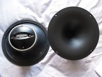
For years I'd wondered why the QSC waveguides performed the way that they do. They don't have an on-axis dip.
Your post explains it : their round waveguide is almost all roundover. The conical part of the waveguide is about 30% of it.
I have a pile of these that I've been unable to sell, but it also feels kinda tragic to dump such a nice waveguide.
Attachments
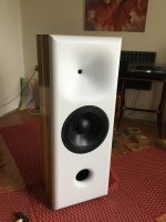
Ro808: From the photo I would think there will be much more serious problems than the driver spacing in that case.
You would think that, like I would, but this guy knows what he's doing.
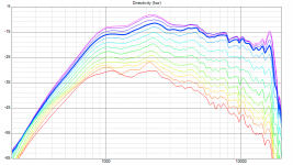
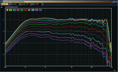
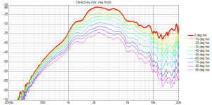
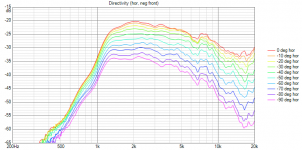
Would you consider this as a smooth enough transition? This is a waveguide of about the size of your Abbeys (12" woofer). The axial problems are also vitually gone (the graph is for 0 - 120 deg / 10). I would put this as my piece of evidence for all the points just mentioned. As for the curve C, I don't know if it is any special but a segment of an Euler spiral (or the curve corresponding to my waveguide formula) works very well as the remedy for most of the problems as you can see.... Do you have examples of a waveguide whose DI drops in a "smooth" way. That's not how I remember things.
I must admit I'm a bit surprised now as I have really considered this as settled facts.
Attachments
Again, this is what hapens if you change the mouth round-over from abrupt to gradual for one particular axisymmetric OS waveguide - I don't know whether the hole is eliminated, went away or diminished to neglibility, but for the best transition it is just not there anymore.
(The picture is an animated GIF and should switch between four plots each 1,5 s.)
(The picture is an animated GIF and should switch between four plots each 1,5 s.)
Last edited:
Data, please 🙂You would think that, like I would, but this guy knows what he's doing.
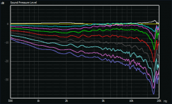
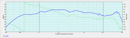
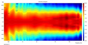
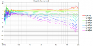
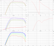
Same measured data as above, EQed for a flat response and normalized to 10 deg. This is still what I would consider a small wavegiude today (and actually the first one that was tried doing it right). Think of what can be done with an 18"! 🙂
Attachments
Last edited:
Same measured data as above, EQed for a flat response and normalized to 10 deg. This is still what I would consider a small wavegiude today (and actually the first one that was tried doing it right). Think of what can be done with an 18"! 🙂
18" should be even better.
For comparison, some plots by BWaslo of the Denovo BA-750 + SEOS 18.
The SEOS' depth is only 15cm, the rectangular mouth is undersized and there's a considerable throat angle mismatch between the BA-750 and the wg, which partly explains the ripple.
Nevertheless, it doesn't look too bad
Apart from a few resonances, the BA-750 doesn't look too shabby either.
I might just score a pair of those.
Attachments
Last edited:
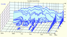
There has been some more results of even smaller waveguides during the recent months, based on my tools - these are some of them from a local Czech forum.
All of it behaves quite well, I'd say.
So it's not completely true that there hasn't been verifications of my work, only the biggest ones are still missing. Basically, today there's really not much to improve on the waveguides alone.
All of it behaves quite well, I'd say.
So it's not completely true that there hasn't been verifications of my work, only the biggest ones are still missing. Basically, today there's really not much to improve on the waveguides alone.
Attachments
Last edited:
- Home
- Loudspeakers
- Multi-Way
- Acoustic Horn Design – The Easy Way (Ath4)