that is correct, you need the phaseplug for the hf polars and loading and you need the waveguide to be huge because of lf directivity control, but also (and for hifi equal important) for huge flaring to reduce mouth reflections
In Norway it is some really “low WAF huge” waveguides under developement with probably the best polar respons i have seen. From 600 Hz and all the way up. For TAD 4003 or JBL2451 with Truextent:
Loftet – superlang byggetrad - Side 549
The Horny Kid - Side 168
Loftet – superlang byggetrad - Side 549
The Horny Kid - Side 168
Last edited:
Why not just 3D print them?
maybe if you can print them solid on a high quality printer with some other material than the standard home-cooking stuff.
With the standard stuf,especially non-solid, it will definately not work very well because of the high losses in the material.
I have measured a lot of printed protoype horns vs the final injected moulds, end those are always having more output, varying from 1-2dB to over 6dB!
but maybe nowadays we can get prints with the same densiity as injection moulding, I don't know the status of the current high tech printers
In Norway it is some really “low WAF huge” waveguides under developement with probably the best polar respons i have seen. From 600 Hz and all the way up. For TAD 4003 or JBL2451 with Truextent:
Loftet – superlang byggetrad - Side 549
The Horny Kid - Side 168
Size seems reasonable compared to the K402.
As regards to WAF, I don't get why people don't mention their hobby when they start dating the (future) "W".
but maybe nowadays we can get prints with the same densiity as injection moulding, I don't know the status of the current high tech printers
Look into nanoscribe, formlabs and others.
Last edited:
Regarding M200 - would be nice use your simulations Marcel to make replacement for 200-2kHz range. There are carbon fiber midranges with closed back.
As Curt Graber (designer of the loudest acoustic speaker system in the world, and perhaps the best midrange compression drivers ever produced) put it to me in a phone conversation 3/22/12, “a compression driver can "go ballistic" on the forward pressure side, but is limited to pulling a vacuum on the negative”.No such target yet. I still don't understand why there should be any difference in this regard (convex vs concave). Aren't the forces the same after all? Isn't it only a coincidence?
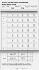
The resistance to compressive forces compared to rarifaction forces regarding convex vs concave can be compared to the bursting and collapsing pressure for pipe.
Looking at the thinnest wall thickness (.065 on the chart below) for 1” pipe, we see a 3/1 ratio in favor of bursting (concave) compared to collapsing (convex).
Going up to 4” pipe, the ratio goes to almost 9/1 using the same wall thickness.
To get down to the 3/1 ratio would require 3 times the wall thickness and weight.
An increase in diaphragm mass reduces high frequency output (mass rolloff).
A reduction in diaphragm thickness increases flex, while diaphragm motion must be limited to about 1mm from the phase plug to reduce the acoustical band pass HF rolloff.
This all leads to a balance between the minimum thickness diaphragm that can withstand the pressures encountered without flexing resulting in contact with the phase plug or too much anti-phase behavior.
Putting the diaphragm in the convex (dome towards throat) compared to the usual concave (dome away from throat) requires a thicker, heavier diaphragm to withstand the forces.
Art
Attachments
maybe if you can print them solid on a high quality printer with some other material than the standard home-cooking stuff.
With the standard stuf,especially non-solid, it will definately not work very well because of the high losses in the material.
I have measured a lot of printed protoype horns vs the final injected moulds, end those are always having more output, varying from 1-2dB to over 6dB!
but maybe nowadays we can get prints with the same densiity as injection moulding, I don't know the status of the current high tech printers
I seal the surface of 3D printed waveguides, just to be safe.
I've 3D printed subwoofers, and the leakiness of the material is *definitely* a problem. You could see it on an impedance sweep, a 3D printed subwoofer behaves like it's aperiodic (due to the air being pushed through the gaps in the layers.) But it's easy to fix, just seal the inner and outer walls.
As far as phase plugs go, I would probably paint the phase plug to seal it, and first I would anneal the print to reduce leakage further.
I could be wrong, but I don't think that a phase plug needs to be metal.
One of the unfortunate issues with 3D printing is that the finer the detail, the weaker the print. IE, if you want a durable print, use a very fat nozzle. Of course, a fat nozzle is the last thing you want when making a phase plug, because the finish needs to be smooth and accurate.
Yeah, but during the waveform there isn't just compression or rarefaction. There's a cycle where the two are repeating one after another. It still seems to me that you are speaking about only a chosen half of it. During the other half the situation is just reversed, isn't it?The resistance to compressive forces compared to rarifaction forces regarding convex vs concave can be compared to the bursting and collapsing pressure for pipe. ...
OK, OK, OK.
Attachments

Last edited:
"Compression drivers are inevitably used with some type of horn. ..."
Yeah, a pity 😀
- So, isn't the driver described the CDX1-1425? I would never have thought that it has a 25 degree conical output wavefront (a diverging one!).
Now I wonder if there ever has been anybody trying the driver that way, i.e. mated to an OS waveguide with 25 deg input angle, which seems like the best match for this driver then.
Last edited:
BTW, the 25 deg seems to be the one-sided value, which gives a 50 deg coverage waveguide (at the throat). Hmm. That could be nice. Why it is not written on the driver?
Edit: No, I got the picture wrong, it will be more like the coverage angle.
Edit: No, I got the picture wrong, it will be more like the coverage angle.
Last edited:


I have a pair of 1425s as well, I only never knew how to use them properly. Now I know... Thanks for the paper, again.
- Yeah, there's a plenty of free space to be damped behind the diaphragm.
This whole driver now makes much more sense to me, after all the time it looked just awkward. It's much closer to what I'm going for now, actually. That's funny.
- Yeah, there's a plenty of free space to be damped behind the diaphragm.
This whole driver now makes much more sense to me, after all the time it looked just awkward. It's much closer to what I'm going for now, actually. That's funny.
Last edited:
And perhaps the absence of ferrofluid?
I'm sure these are nice tweeters (after some modifications), but apart from the construction, the one thing that really interests me is the diaphragm material.
I'm sure these are nice tweeters (after some modifications), but apart from the construction, the one thing that really interests me is the diaphragm material.
Last edited:

- Home
- Loudspeakers
- Multi-Way
- Acoustic Horn Design – The Easy Way (Ath4)