Bonsai horns cute.

My impression after reading way too many Synergy/Unity/MEH threads is that a lot of builders find that putting the ports in the corners doesn't offer as much advantage as expected, and in some cases it makes construction harder. I don't have direct evidence one way or the other, because I've only gone the "in the corners" route. I'm in the process of printing a cylindrically symmetric horn where the corners question is moot so I'll soon find out if I'd be better off with corners to hide midrange ports in. Even the rule that ports shouldn't be closer to the compression driver than lambda/4, where lambda is the wavelength of sound at the midrange's upper frequency limit, seems to have lost some of its Holy Commandment status.
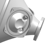
I'm going to try the blend of volume filling and "frustrumizing" shown in the attached image (midrange driver: B&C 4NDF34). The wavelength at my target crossover frequency of 1250 Hz is ~27 cm so my guess is that some of the fine details of the frustrum shape don't matter unless they cause noisy turbulence of some sort. But no frustrum may yield a Helmholtz resonator with a frequency that's lower than intended. Again, I can't prove any of this; they're just working assumptions that I may come to regret! The Helmholtz part seems pretty well established by others, though.
Few
Attachments
It's the real deal.... A guy put up a good disassembly thread...lots of pics. Wish I had the link to give...
.


fwiw, on my builds i haven't really found it makes difference, stepped vs frustrum...round vs oval etc.
Maybe it matters a lot at very high-spl, but I seldom measure there. And maybe with passive, it's more important to get as close as possible to needing less corrections....
.
fwiw, on my builds i haven't really found it makes difference, stepped vs frustrum...round vs oval etc.
Maybe it matters a lot at very high-spl, but I seldom measure there. And maybe with passive, it's more important to get as close as possible to needing less corrections....
My impression after reading way too many Synergy/Unity/MEH threads is that a lot of builders find that putting the ports in the corners doesn't offer as much advantage as expected, and in some cases it makes construction harder. I don't have direct evidence one way or the other, because I've only gone the "in the corners" route. I'm in the process of printing a cylindrically symmetric horn where the corners question is moot so I'll soon find out if I'd be better off with corners to hide midrange ports in. Even the rule that ports shouldn't be closer to the compression driver than lambda/4, where lambda is the wavelength of sound at the midrange's upper frequency limit, seems to have lost some of its Holy Commandment status.
My take on it is that locating ports in the corners is generally best practice if you're using a traditional pyramid shaped conical horn with flat walls, and round or oval shaped ports. The theory being that the corners are more "dead" than the walls and will cause less harmful diffraction. As soon as you move toward any other sort of horn profile or a waveguide all bets are off though as the distribution of sound energy inside the horn can change and the "corners" may no longer be dead zones.
I've started a new habit of setting up an observation field (sphere) in akabak with every new MEH where the radius of the sphere equals the 1/4 wavelength @ crossover frequency to approximate where the ports will be. Wherever the sound energy is lowest (generally in the 3-8kHz frequency region) is where I'll place the ports. So in the below example of a profile generated in Ath, you can see that the corners may actually not be the most ideal spot, and the middle of the walls would be better.
Whereas the below example shows a pyramid shaped conical horn where the opposite might be true:
Right now the challenge is figuring out exactly what frequencies are important to look at in the observation field as there can be some variation, but in theory you can calculate where the lobes/cancellations from diffraction would occur, and use that to inform some more decisions around port placement. I'm working on a more thorough writeup with data/physical prototypes to back up these claims, but figured I'd share since there's a lot of interest lately in 3d printing MEHs and depart from the traditional conical shapes.
They certainly areThe ATH-generated waveguides are so good.
I had this problem with my previous attempts, but I believe I fixed it with the current Area-51 version.I have been wondering about measurements either before the midrange ports are cut or with them covered. You don't happen to have those, do you? It would be very interesting to compare them with the graphs in your second attachment.
I've attached some measurements and photos of the previous version. I was lazy with the design and extended the midrange taps/ports far enough so everything could be mounted flat...
I thought another user kinda solved this the last time.. I could be wrong however..
If the pic with the MF driver removed and the ones @mark100 posted are both from SH50s, could it be the taps are drilled at an angle, thus appearing more central on the outside, and in the corners on the inside?
Added: excellent close ups btw..
I've no complaints on both my SH50 and SH60 alikes where it comes to HF horn sound (with the taps firmly in the corners) - but I've never heard them any other way.
All I can compare them to are the
Tractrix 400 / 550Hz and Le Cléach 550Hz round horns of systems yore..
Last edited:
Maybe I'm wrong, but, shouldn't be opposite?Even the rule that ports shouldn't be closer to the compression driver than lambda/4, where lambda is the wavelength of sound at the midrange's upper frequency limit
I thought the latest was just to get them all as close as possible.
Would seem to make sense if one is DSP time delaying anyway..
Would seem to make sense if one is DSP time delaying anyway..
Hi all, I've just put together some measurements for the Tritonia XS for my ongoing project - HERE
Measurements include:


Thanks again, Marcel!
Measurements include:
- Freestanding
- 25mm Radius Surround
- Baffle mounted
Thanks again, Marcel!
I thought the latest was just to get them all as close as possible.
Would seem to make sense if one is DSP time delaying anyway..
Being the simplistic minded dude I am, I see port placements as having three basic balancing objectives.
The one I pay most attention to is keeping all ports withing 1/4WL of each other throughout their summation ranges.
Next has been the 1/4 WL notch cancellation, mids to CD....staying within that..so closer means better if higher notch is needed.
Last is low frequency cut-off and efficiency gain, along the lines of this chart from DSL website ago.
I try to put ports in corners per standard advice, but I've been willing to sacrifice that primarily for weight savings. Can save a LOT of weight...
Indeed; thanks for the correction! The rule is supposed to be ports should not be farther than lambda/4. Typing too quickly apparently. I'd like to think that explains my tapered port misspelling as well... Very frustating.Maybe I'm wrong, but, shouldn't be opposite?
Few
@grahamgraham - That's a very nice implementation, Graham. The graphs are a bit too smoothed to my taste but it's quite clear that the performance is basically flawless.
@mabat You're right, 1/48 smoothing with 2.5ms gate! Did them in a rush so forgot to turn variable smoothing off!
Still looks great doesn't it.

Still looks great doesn't it.
This thread is AWESOME!
I'd k!ll for some Danley Jericho's.
I see only a few fit through a standard door.
I'd k!ll for some Danley Jericho's.
I see only a few fit through a standard door.
crazy that a 50 euro driver could behave like this@mabat You're right, 1/48 smoothing with 2.5ms gate! Did them in a rush so forgot to turn variable smoothing off!
Still looks great doesn't it.
View attachment 1458068
@mabat do you see any chance to modify a tritonia waveguide in order to fit 4 low/midranges in the corner just like done at the Genelec 9381a? Maybe morphing the existing shape is already possible with ATH but if....then my knowledge is too limited. Looking at this concept I think it is an interesting alternative to a MEH.
That's made possible by the coaxial driver in the throat. There's no point with a regular compression driver. You would have to do a two-way MEH first, and then add those corner radiators. Frankly, I don't like the difficulty.
I just did a quick (very very rough!!!!) estimation with direct sound for 12cm LF drivers in 46cm diameter with a best-guess center speaker and XO @700Hz. From dispersion angle I end up with ~28° for -3db. That looks not far away for a BMS 460G2 extended. So a XO of 700Hz could be doable. If I find some time I would try to make a proper 3D model and give a more detailed try.
The Genelec is crossed at 500 and 1800Hz regarding datasheet. So coax XO is the 1800Hz one..... 500 Genelec vs. 700 for BMS extended.....not so far away....
The Genelec is crossed at 500 and 1800Hz regarding datasheet. So coax XO is the 1800Hz one..... 500 Genelec vs. 700 for BMS extended.....not so far away....
- Home
- Loudspeakers
- Multi-Way
- Acoustic Horn Design – The Easy Way (Ath4)