For years, I've been struggling to get consistent results from ABEC. Basically, sometimes I run a sim and the curves look spectacular, and other times they look like complete nonsense.
I've upgraded my hardware and bought piles of RAM and that's helped me produce sims that extend to 16khz and higher, but I still have issues where I'll run a sim for seven hours and the results are nonsensical.
My 'hunch' is that one of these reasons may be related to ABEC subdomains, but I'm struggling to understand what they do and why they're there.
From the manual:
"So far we didn't care about the BEM subdomain interfaces as described in 3.1.1. By default one subdomain interface is automatically placed at the end of the profile, separating the interior of the horn and the exterior subdomain. In a case of an infinite baffle simluation there must always be an interface enclosing the elements "behind" the baffle, i.e. there must be at least one interface for this purpose. For free standing horns this interface can be manually placed anywhere along the length or even left out completely (then the only subdomain left is the exterior). In both cases we can add as many interior subdomains as we like."
I believe I've found a "fix" for my issues; I'm just not sure why this fix works:
Basically, to get good results, I've been adding an "offset" entry under the stanza "ABEC.POLARS" and the offset is equal to the distance from the throat to the mouth, plus one millimeter. IE, if the waveguide is 99mm deep, I set "offset" to 100mm in the stanza "ABEC.POLARS"
This solution also requires me to do my sims as infinite baffle; I'm not entire sure if the "offset" line is required for "freestanding" ABEC sims and I'm not sure if the subdomains are required either.
Anyone have any insight?
TBH, part of the reasons I haven't used ATH to make much stuff on my 3D printer is because the results of my sims have been so inconsistent. And I'm 99% sure they're inconsistent because of the issues described above.
Basically, when I just make a waveguide in 3D using nothing but plain ol' geometry, the measured results have been generally good. But when I attempt to model THE EXACT SAME WAVEGUIDE using ATH and ABEC, the results are often random and unpredictable.
I don't remember, the slicer says 2h 43m, it might have been a little bit more - I use an old printer, 80 mm/s, 1000 mm/s^2.How long was the printtime for one petal with your settings?
Last edited:

I wrote an email.QC issues indeed?
The DFM-2535R00-08 has a specified frequency range of 1.5 - 15 kHz, and inconsistencies around 1 kHz may be acceptable to the manufacturer in terms of defined output quality.
Hi everyone
I'm building the 460G2 horns and will be removing the bug screen from the the CD so I can use the throat adaptor. I've read that this can lead to problems with dust / insects getting into the CD. Has anyone tried, or have a view, on inserting a new bug screen in the horn throat to protect the CD?
Apologies if this has been asked before.
PA
I am not sure what you are using the horn for, but removing the bug screen on the CD might be a good thing. Some manufacturers use a screen that could stop a bullet, but causes reflections that can be seen in the FR response. One of the things I noticed about the DFM-2535 is it has a very minimal screen, which I think is one of the reasons for the smooth top end. I would replace the CD screen with a very fine nylon screen on the adapter if you think you need it.
For years, I've been struggling to get consistent results from ABEC. Basically, sometimes I run a sim and the curves look spectacular, and other times they look like complete nonsense.
I've upgraded my hardware and bought piles of RAM and that's helped me produce sims that extend to 16khz and higher, but I still have issues where I'll run a sim for seven hours and the results are nonsensical.
My 'hunch' is that one of these reasons may be related to ABEC subdomains, but I'm struggling to understand what they do and why they're there.
From the manual:
"So far we didn't care about the BEM subdomain interfaces as described in 3.1.1. By default one subdomain interface is automatically placed at the end of the profile, separating the interior of the horn and the exterior subdomain. In a case of an infinite baffle simluation there must always be an interface enclosing the elements "behind" the baffle, i.e. there must be at least one interface for this purpose. For free standing horns this interface can be manually placed anywhere along the length or even left out completely (then the only subdomain left is the exterior). In both cases we can add as many interior subdomains as we like."
I believe I've found a "fix" for my issues; I'm just not sure why this fix works:
Basically, to get good results, I've been adding an "offset" entry under the stanza "ABEC.POLARS" and the offset is equal to the distance from the throat to the mouth, plus one millimeter. IE, if the waveguide is 99mm deep, I set "offset" to 100mm in the stanza "ABEC.POLARS"
This solution also requires me to do my sims as infinite baffle; I'm not entire sure if the "offset" line is required for "freestanding" ABEC sims and I'm not sure if the subdomains are required either.
Anyone have any insight?
TBH, part of the reasons I haven't used ATH to make much stuff on my 3D printer is because the results of my sims have been so inconsistent. And I'm 99% sure they're inconsistent because of the issues described above.
Basically, when I just make a waveguide in 3D using nothing but plain ol' geometry, the measured results have been generally good. But when I attempt to model THE EXACT SAME WAVEGUIDE using ATH and ABEC, the results are often random and unpredictable.
Attached is an example of what I was talking about; note the insane amounts of comb filtering in the simulated response.
Attachments
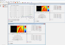
This happens when something has gone with the mesh or program and the solver cannot come to a correct answer. It can be from a bad mesh or I have had it happen to me when I changed my computer and there was some drama between ABEC and the version of Windows I was running. Sometimes turning NUC on and off in different combinations fixed it and the same project that produced that type of garbage then solved properly.Attached is an example of what I was talking about; note the insane amounts of comb filtering in the simulated response.
If you do a search for NUC in this thread you might find the discussion.
Is there anything to be done to fix the rubbing? I just disassembled the driver, found no wiggle room to move the diaphragm relative to the housing, and on reassembly there is no change in the impedance trace.I would consider the yellow one OK, the red one rubbing.
I suspect you are correct, and we have been expecting too much perfection from what is ultimately an inexpensive compression driver. I'll make what I have work for now and concentrate on perfecting my 3D printing and horn assembly and finishing. I may wind up using an A400/460G2 horn that can be used with various adapters rather than the hypothetical dedicated 2535 version.The DFM-2535R00-08 has a specified frequency range of 1.5 - 15 kHz, and inconsistencies around 1 kHz may be acceptable to the manufacturer in terms of defined output quality.
anyone had success making a very short horn? im looking for something i can fit into my kick panels. maybe the tritona? im not even sure what coverage would be best.
Car audio? Any how, wouldn't a waveguide suffice?anyone had success making a very short horn?
If possible, could you repeat distortion measurements for higher SPL, for example 86, 96, 105?Distortion seems well in control:
Thanks so much. It would be helpful to have a series at several SPL levels and see how distortion behaves with increasing excursion. Not to burden you too much, but if you can do it with both of your drivers we can say with certainty if it is a technical issue.
Wound up having some time tonight so here we go. My two drivers are now mounted on the Autotech Iwata horns, so I ran sweeps on them as they were. The Iwata gives a nice, smooth frequency response that goes lower than the baby ATH horn, so I thought it was suitable for this purpose.
I use an old Dayton EMM-6 mic and a Motu M2 interface. The mic was placed 1 meter from the outlet flange of the driver directly on axis. No l-pad or cap was used in between the amp (Neurochrome Modulus 86) and the driver.

I ran three sweeps on each driver, at roughly 86, 96 and 106 dB, as measured by my Radio Shack SPL meter.
Here are the six frequency responses, with a 3 ms gate:

The 2dB dip at 1kHz in one driver is consistent at all levels, and also consistent with the difference I saw on the ATH horn.
Distortion measurements in the next post.
I use an old Dayton EMM-6 mic and a Motu M2 interface. The mic was placed 1 meter from the outlet flange of the driver directly on axis. No l-pad or cap was used in between the amp (Neurochrome Modulus 86) and the driver.
I ran three sweeps on each driver, at roughly 86, 96 and 106 dB, as measured by my Radio Shack SPL meter.
Here are the six frequency responses, with a 3 ms gate:
The 2dB dip at 1kHz in one driver is consistent at all levels, and also consistent with the difference I saw on the ATH horn.
Distortion measurements in the next post.
Now the distortion measurements. First the 'good' driver:


Now the suspect driver:


There is clearly something bad going on at 1 kHz. Whether that is actually VC rubbing or some kind of suspension resonance I don't know. Will Tymphany regard a 10 dB spike in distortion outside of their stated frequency range as a warrantable defect?
Now the suspect driver:
There is clearly something bad going on at 1 kHz. Whether that is actually VC rubbing or some kind of suspension resonance I don't know. Will Tymphany regard a 10 dB spike in distortion outside of their stated frequency range as a warrantable defect?
Two more graphs, this time relative distortion in dB for the two drivers at the 96 dB drive level, with the harmonics displayed at the harmonic frequency:


What does this say about the audibility of the difference?
For those that might want it, an REW .mdat file is attached with all six measurements.
What does this say about the audibility of the difference?
For those that might want it, an REW .mdat file is attached with all six measurements.
Attachments
BTW, should this discussion be split off to its own thread, to keep this thread focused on mabat's work rather than a specific driver?
Interestingly, these results aren't what I'd expect from a rubbing voice coil. Typically you'd see significantly elevated high-order harmonics (especially odd orders).Now the distortion measurements.
- Home
- Loudspeakers
- Multi-Way
- Acoustic Horn Design – The Easy Way (Ath4)