Anyone have any advice or experience with sizing a capacitor to protect the compression drivers here? I'm thinking I'll cross at around 650 Hz actively. I've read maybe put a cap in to have a HP 1.5 octaves below your expectec xo point, which would put me at about a 100 uF cap but wanted to hear what others had employed.
I'm driving it with a 2A3 Tube amp if it makes a difference.
I'm driving it with a 2A3 Tube amp if it makes a difference.
Last edited:
IHMO I would go for a small cap.
Beter protection
First order crossover at higher frequency that flatten the response
Cheaper
Beter protection
First order crossover at higher frequency that flatten the response
Cheaper
Sorry I should have clarified - the SB Audience Rosso 65CDN-T, 8 Ohm.
https://www.sbaudience.com/index.php/products/compression-drivers/rosso-65cdn-t/
I'm going active for the crossover so I'd like to keep it out of the crossover range unless there is a compelling reason to do so.
https://www.sbaudience.com/index.php/products/compression-drivers/rosso-65cdn-t/
I'm going active for the crossover so I'd like to keep it out of the crossover range unless there is a compelling reason to do so.

Well the honest answer is that I have zero experience designing passive crossovers, so I'd prefer to have the flexibility over the whole range to try to tweak / adjust as needed. Really, this is just to protect the driver in the event of a DSP failure or amplifier thump.
Try yourself: https://www.v-cap.com/speaker-crossover-calculator.php#firstOrderCalculator
This one requeis you to add a LF driver - add the same impedance as the CD. You can of course just ignore the LF part result as you wont use it.
You should probably use the CD impedance att he desired XO frequency - read the data sheet.
My reccomedation is to use these: https://www.mouser.se/ProductDetail/WIMA/MKP1G051007J00JSSD?qs=dTJS0cRn7oi0MrvUVxo8lg==
Paralleling them adds capacitance. You might need 3-4 per driver....
//
Last edited:
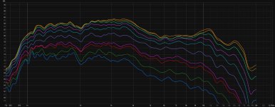
This is a quick sim with the on-axis found in @mabat website
https://at-horns.eu/gen2m.html#rosso65cdnt
In Room Eq Wizard, the target is 87dB and LR24 at 650Hz then a 6dB high pass at 1800Hz.

Then at 400Hz.

However for the first, you must already know your xo point and slope...
https://at-horns.eu/gen2m.html#rosso65cdnt
In Room Eq Wizard, the target is 87dB and LR24 at 650Hz then a 6dB high pass at 1800Hz.
Then at 400Hz.
However for the first, you must already know your xo point and slope...
Why use a capacitor to protect the driver? You write you use 2A3 tube amp with an active crossover to avoid using passive components. I am guessing now, but it will have a output transformer, so no danger of DC on the outputs. Also with 2,5 watts of tube power, you won't damage a driver that can handle 140 watts even with a LF thumb (a well designed tube amp will not "thumb" when switched on or off). There are other events that might create a "thumb" but the driver will likely not be damaged by that, although it might sound nasty and scary. The best capacitor is no capacitor in my opinion. Disclaimer: no guarantee from me, so decide for yourself if the risk is worth it.Anyone have any advice or experience with sizing a capacitor to protect the compression drivers here?
@Patrick Bateman
I ran into similar issues last year when i was optimizing my M2 type waveguide (yeah still haven´t given up on those) for a N151M, running very similar hardware to yours. The fastest way was to only ever play with mesh granularity and frequency range. Running tons of simulation from 500 to 14k with mesh size optimized for these results and then concentrating the effort on 14k up with way finer mesh and doing one fullrange simulation in the end to verify.
I am not sure i have drawn the right conclusion from my efforts, but yesterday i finally came around doing a quick and dirty measurement of my waveguide and cabinet. No EQ, 12th smoothing, 500mm distance, 0 - 90°.
Attachments
I would refrain from doing it until you know exactly what you're doing. A single series capacitor is seldom a good thing. You would need to measure the electrical impedance (as a fuction of frequency) and the acoustic response and design a passive filter based on that. It's not difficult (in a simulator) but you must know what you're doing and be able to check the results, otherwise it can end up being far worse than without a cap, as any impedance peaks can translate directly into (new) frequency response peaks. I would never put a large capacitor there - you want high-quality stuff and big capacitors are expensive. And there's absolutely no need for that.Anyone have any advice or experience with sizing a capacitor to protect the compression drivers here? I'm thinking I'll cross at around 650 Hz actively. I've read maybe put a cap in to have a HP 1.5 octaves below your expectec xo point, which would put me at about a 100 uF cap but wanted to hear what others had employed.
I'm driving it with a 2A3 Tube amp if it makes a difference.
Last edited:
Depending on amplifier there might be audible hiss. In which case you'd want to add a resistor or L-pad in series with the driver to reduce the hiss. This would also make the impedance peaks as peaks in frequency response, just like the cap but perhaps bit less. These can be mitigated with DSP, but cap and / or resistors reduce electrical damping of the resonances though, so might affect sound quality some.
You can restore some electrical damping using just a series resistor instead of L-pad, and inductor in parallel with driver. This works as high pass filter, doesn't kill all the electrical damping, and reduces the amp noise. Use DSP to make the acoustic response what ever needed.
The parts don't cost much, so I recommend experimenting with this stuff. Perhaps there is audible difference in one application, while not on another.
Last edited:
Thanks all for the advice - I think for the moment I'm going to forego the protective cap and just run it all through DSP. While there is likely some risk I'll take it given the tradeoffs.
I do all my measurements without any protective caps, even full-range sweeps are not an issue for any sane SPL. I can't imagine what would need to happen so that I destroyed the driver... (Well, maybe the sweeps are not really full range, maybe like from 100 or 200 Hz, I'm not sure now...)
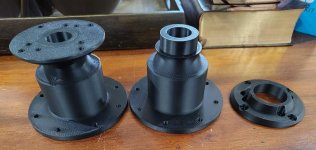
A few pics from a recent build. This is an alternative waveguide for the TAD ET703. Profile was designed in Ath, initial prototype for testing was 3D printed, and final version with the smooth baffle transition was modeled in fusion/validated in Akabak before being machined from walnut.


Attachments
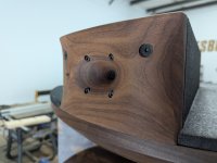
Thanks! The finish is Osmo 3054.
Midrange entries would be an interesting challenge at a 5khz crossover!
Midrange entries would be an interesting challenge at a 5khz crossover!
Really nice! 🤩 Do you have any measurements?A few pics from a recent build. This is an alternative waveguide for the TAD ET703. Profile was designed in Ath, initial prototype for testing was 3D printed, and final version with the smooth baffle transition was modeled in fusion/validated in Akabak before being machined from walnut.
View attachment 1434695View attachment 1434696View attachment 1434697View attachment 1434698View attachment 1434699View attachment 1434701
- Home
- Loudspeakers
- Multi-Way
- Acoustic Horn Design – The Easy Way (Ath4)