I think I may have found the culprit for a problem that's made ATH basically unusable for me.
If anyone has any suggestions, solutions, please clue me in.
Here's the issue:
1) I have basically zero interest in waveguides unless they're in a speaker enclosure. I know that ATH can make some very nice freestanding waveguides, but I really need something that I can install in a baffle, because WAF
2) The issue I've been seeing, is that the high frequencies of my ATH sims look TERRIBLE:
(See second attachment, named "ath 1000Hz.jpg")
According to the prevailing knowledge on this forum, "ABEC.MeshFrequency" should be set to 1000Hz.
What I found, is that the simulation of the top octave improves DRAMATICALLY if I increase "ABEC.MeshFrequency" to 20,000Hz.
(See first attachment, named "ath 20000.jpg")
That would be a viable solution, except IT TOOK FOURTEEN HOURS to run the sim. That was with fourteen E5 Xeon cores and 96GB of RAM.
Third attachment is the config file.
Attachments

The whole idea of setting 'ABEC.MeshFrequency=1000' (i.e. a very low value) is to make ABEC to not perform any further subdivisions. But then the mesh resolution must be high enough to begin with. So, if the mesh turns out not to be good enough for the frequency range of interest, increase the mesh resolution in the first place (by setting the items Mesh.*Resolution [mm]).
Setting ABEC.MeshFrequency to a high value has a similar efect in the end, but the drawback is that it doesn't further improve the accuracy of the mesh shape itself, contrary to the other way. It's just a suboptimal way of doing it. With Mesh.*Resolution you can also set different values for different places of the model - typically, you can save quite a lot of elements this way.
You can also split the calculation into several frequency bands with limited number of frequency points in each, with different mesh densities.
Last edited:
Here's some additional ideas on how to deal with this problem:
1) Instead of running my sims to 16khz, I can run them to 10khz, and then once things start to look good, I can crank the MeshFrequency up from 1khz to 20khz
2) I don't understand how "remeshing" works. According to the ATH docs, "The best practice is to make the mesh resolution high enough by setting the Mesh.*Resolution so that ABEC won't need (and won't do) further re-meshing. If this value is increased, ABEC may perform some additional meshing by subdividing the existing one. Note: For the Circular Symmetry mode this value should be increased considerably, at least to 30000 Hz"
Something I've noticed, which I don't understand, is that if you look at the tweeter in the ABEC sim, the resolution of the tweeter mesh is way higher than what's specified in the config file. For instance, I have "Mesh.ThroatResolution" set to 3mm, but the mesh of the tweeter itself seems much higher than that.
I assume there's some parameter that sets the resolution of the tweeter diaphragm itself, but I'm not sure what that parameter is.
The whole idea of setting 'ABEC.MeshFrequency=1000' (i.e. a very low value) is to make ABEC to not perform any further subdivisions. But then the mesh resolution must be high enough to begin with. So, if the mesh turns out not to be good enough for the frequency range of interest, increase the mesh resolution in the first place (by setting the items Mesh.*Resolution [mm]).
Setting ABEC.MeshFrequency to a high value has a similar efect in the end, but the drawback is that it doesn't further improve the accuracy of the mesh shape itself, contrary to the other way. It's just a suboptimal way of doing it. With Mesh.*Resolution you can also set different values for different places of the model - typically, you can save quite a lot of elements this way.
You can also split the calculation into several frequency bands with limited number of frequency points in each, with different mesh densities.
Thanks Mabat, I'll try that
Have you tried something in between, like "ABEC.MeshFrequency" to 10,000Hz?
See Mabat's comment above; it looks like I'm doing things wrong.
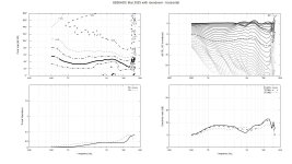
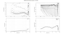
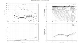
Attached is a comparison of the sims at 1000Hz, 4000Hz, and 20000Hz. You can see that the top octave doesn't get "well behaved" until I set ABEC.MeshFrequency to 20Khz-ish.
Attachments

Thanks John, I appreciate your offer to have a look.@cowanaudio post your config and I'll run it on my end and see what happens.
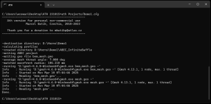
I've attached the screen grab of the result and the file I was running. I renamed Demo1.cfg to Demo1.txt to upload here, but it still appears to work in ATH as a txt file. This file is the demo in the documentation. Turning the abec file on and off doesn't appear to change the result. It does generate an stl for me. I've also tried the Tritonia-S file from Marcel's website with the same result.
I haven't installed ABEC yet, but all other required programs appear to have installed correctly.
My ath.cfg file points to the correct location for gmsh and gnuplot.
Many thanks for any help you can offer.
Attachments
calculation + results optimized would be if ath would script a double simulation run: first with low mesh (i.e. 1000) for 0-15kHz, store abec results, second with high mesh count for 15-20kHz, combine. and prepare combined output data + plots.
Problem solved by rolling back to ATH 4.8.3b2
I'm not sure why the current version didn't work. I DL'd it again, with no luck.
For anyone interested this is my setup:
Win11
Gmsh V4.6.0 Win64
ABEC_Demo_v360b07
gnuplot 6.0 patch 2
VACSviewer 64 v213b33
I'm not sure why the current version didn't work. I DL'd it again, with no luck.
For anyone interested this is my setup:
Win11
Gmsh V4.6.0 Win64
ABEC_Demo_v360b07
gnuplot 6.0 patch 2
VACSviewer 64 v213b33

Any measurements for the A460G2 with the 36-EXT throat? I only found some with the 520 horn here:
But quite disappointing results compared to the STD throat.
T520-36-EXT-type-B looks good though, but can't find any details on that.
Hi @mabat, I finally got to test the last version of the adapter.
The measurements aren't accurate, I shoot the ceiling again and just rearrange the adapters.
6 cycles window, 5dB step, mic is always at the same distance from the driver (~90cm), and I tried to place the horn in the same place (so I don't think the difference in the top end is due to microphone/horn position, it was seen on other measurements as well).
T520-36-STD-1 - green
T520-36-EXT-1 - blue
T520-36-EXT-type-B - orange

Group delay:

The measurements aren't accurate, I shoot the ceiling again and just rearrange the adapters.
6 cycles window, 5dB step, mic is always at the same distance from the driver (~90cm), and I tried to place the horn in the same place (so I don't think the difference in the top end is due to microphone/horn position, it was seen on other measurements as well).
T520-36-STD-1 - green
T520-36-EXT-1 - blue
T520-36-EXT-type-B - orange
Group delay:
But quite disappointing results compared to the STD throat.
T520-36-EXT-type-B looks good though, but can't find any details on that.
Last edited:
Anyone tried to sketch (or even build) a scaled bigger version of the A520G2?
Reason of the question is just to find a reasonable solution to be used with DCM50 2” drivers, target would be reaching 350-400hz, if it isn’t too ambitious… 😀
Reason of the question is just to find a reasonable solution to be used with DCM50 2” drivers, target would be reaching 350-400hz, if it isn’t too ambitious… 😀
The only effect of an increased size of a Gen2 device would come from the narrowed beamwidth towards the lower frequencies. I'm still not sure about how to calculate the corresponding on-axis SPL gain, but my guess is that this wouldn't be so substantial.
- That said, I have A620G2 in the making 🙂

- That said, I have A620G2 in the making 🙂
BTW, any experience with Celestion CDX14-3055?
It seems they really know their stuff. I was truly amazed by the CDX1-1720 - it's so much better than most of what I've seen.
Now if only the bigger version was nearly as good...
It seems they really know their stuff. I was truly amazed by the CDX1-1720 - it's so much better than most of what I've seen.
Now if only the bigger version was nearly as good...
Last edited:
I tried what @mabat recommended yesterday, and that seemed to work (no surprise.)
Basically:
1) my sims had high frequencies that looked terrible
2) when I increased my "meshfrequency" to 20khz, the high frequencies looked great, but the sim took fourteen hours
3) when I kept "meshfrequency" at Mabat's recoomendation (1khz) but increased the granularity of the mesh, the high frequencies looked great, but it took seven hours
So, basically, follow Mabat's advice. Use a meshfrequency of 1khz. I'd add a caveat that "if your high frequencies look like a mess," consider increasing the granularity of your mesh.
"A picture is worth a thousand words."
Here's a comparison of two sims; there are a handful of changes between sim 1 and sim 2, but I believe the main difference is that the one that looks good has a 2mm resolution at the throat and the one that looks bad has a 2.5mm resolution at the throat. Just half a millimeter of difference!!
And to put that in perspective, 14khz is 24mm long.
So we're talking about a resolution of 8% of wavelength versus 10% of a wavelength!!
Having said that, I've made plenty of waveguides IRL, where a difference of 2-3mm made a difference at the throat.

Here's the one that looks messy. Note that the scale on this one is twice has wide as the other one.

Here's the one that looks better. Note that the scale on this one is half as large as the first. Of particular note is that the highs don't look CRAZY.
Here's a comparison of two sims; there are a handful of changes between sim 1 and sim 2, but I believe the main difference is that the one that looks good has a 2mm resolution at the throat and the one that looks bad has a 2.5mm resolution at the throat. Just half a millimeter of difference!!
And to put that in perspective, 14khz is 24mm long.
So we're talking about a resolution of 8% of wavelength versus 10% of a wavelength!!
Having said that, I've made plenty of waveguides IRL, where a difference of 2-3mm made a difference at the throat.
Here's the one that looks messy. Note that the scale on this one is twice has wide as the other one.
Here's the one that looks better. Note that the scale on this one is half as large as the first. Of particular note is that the highs don't look CRAZY.
| Bad | Good |
| ; ------------------------------------------------------- ; Mesh Setting ; ------------------------------------------------------- ; ABEC Mesh.CornerSegments = 8 Mesh.ThroatResolution = 2.5 Mesh.MouthResolution = 8 Mesh.Subdomainslices= ;Mesh.InterfaceOffset = 5.0 ; ------------------------------------------------------- Mesh.Enclosure = { Spacing = 64, 256, 64, 256 Depth = 200 ;EdgeRadius = 38.1 ;EdgeType = 1 FrontResolution = 12,12,12,12 BackResolution = 24,24,24,24 } Mesh.Quadrants = 1 Mesh.LengthSegments = 38 Mesh.AngularSegments = 72 Mesh.SubdomainSlices = ; ------------------------------------------------------- ; ABEC Project Setting ; ------------------------------------------------------- ABEC.SimType = 2 ABEC.f1 = 450; [Hz] ABEC.f2 = 14400 ; [Hz] ABEC.NumFrequencies = 61 ABEC.MeshFrequency = 1000 ; [Hz] | ; ------------------------------------------------------- ; Mesh Setting ; ------------------------------------------------------- ; ABEC Mesh.CornerSegments = 8 Mesh.ThroatResolution = 2 Mesh.MouthResolution = 9 Mesh.Subdomainslices= ;Mesh.InterfaceOffset = 5.0 ; ------------------------------------------------------- Mesh.Enclosure = { Spacing = 64, 256, 64, 256 Depth = 200 EdgeRadius = 38.1 EdgeType = 2 FrontResolution = 12,12,12,12 BackResolution = 18,18,18,18 } Mesh.Quadrants = 1 Mesh.LengthSegments = 38 Mesh.AngularSegments = 72 Mesh.SubdomainSlices = ; ------------------------------------------------------- ; ABEC Project Setting ; ------------------------------------------------------- ABEC.SimType = 2 ABEC.f1 = 450; [Hz] ABEC.f2 = 14400 ; [Hz] ABEC.NumFrequencies = 61 ABEC.MeshFrequency = 1000 ; [Hz] |
I can try one with a 1.4" faital hf1440 to measure the low kneeThe only effect of an increased size of a Gen2 device would come from the narrowed beamwidth towards the lower frequencies. I'm still not sure about how to calculate the corresponding on-axis SPL gain, but my guess is that this wouldn't be so substantial.
- That said, I have A620G2 in the making 🙂
View attachment 1433387
The message was that the larger waveguide won't load the driver any better. It's a common misconception (if this was the idea).
There will be some gain due to the narrowed beamwidth, but probably not that much. When I measure the A400G2 and A520G2 with the same driver, the difference is there but still pretty small, IMO.
There will be some gain due to the narrowed beamwidth, but probably not that much. When I measure the A400G2 and A520G2 with the same driver, the difference is there but still pretty small, IMO.
Last edited:
This is very interesting, i also want to try A520 with my dcm50 🙂 please share if you will be first, thanksAnyone tried to sketch (or even build) a scaled bigger version of the A520G2?
Reason of the question is just to find a reasonable solution to be used with DCM50 2” drivers, target would be reaching 350-400hz, if it isn’t too ambitious… 😀
- Home
- Loudspeakers
- Multi-Way
- Acoustic Horn Design – The Easy Way (Ath4)