
BTW, I've printed and tested this (link) already - it wasn't better but I need to do all of this again in a bigger reflection-free space to make valid conclusions.
Last edited:
I've been partly successful in simulating/reproducing those narrow midrange wiggles -


This was one of the hypotheses, that the bigger horns are better in shadowing these reflections.
This was one of the hypotheses, that the bigger horns are better in shadowing these reflections.
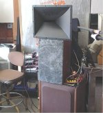
as they going down to 20ies with very small boost I lost little bit of sensitivity, that is allAre the 15 inch cabinets are too small? Great fr btw
raw response
Mabat, I'm sorry if this has been gone over before.
I want to scale the A520G2 to 610mm. But I don't quite understand where I should start the scaling from - I assume the throat part could stay the same. Can you point me in the right direction? Thanks.
I want to scale the A520G2 to 610mm. But I don't quite understand where I should start the scaling from - I assume the throat part could stay the same. Can you point me in the right direction? Thanks.
Yes, you could scale the profile curve so that the throat radius stays the same, i.e. keep that point fixed.
I don't know what it does exactly in terms of acoustic performance (it's not just a different scale) but I assume it's still fine.
I don't know what it does exactly in terms of acoustic performance (it's not just a different scale) but I assume it's still fine.
Last edited:
That's a weird graph for a raw response. Didn't you use a series capacitor, or something?raw response
Here's another example. The disc behind the horn has a ring source, as an emulation of a reflection. The horn itself doesn't radiate anything here, it's just there as an obstacle (with a closed throat).

This is with the horn removed, i.e. just the disc - polars 0 - 45 / 5deg @ 1m:

And this is with the horn present:

So, obviously, it's a good idea to avoid or eliminate any axisymmetric reflection sources behind the horn...
Maybe we should pay a lot more attention to the back sides of the horns afterall.
This is with the horn removed, i.e. just the disc - polars 0 - 45 / 5deg @ 1m:
And this is with the horn present:
So, obviously, it's a good idea to avoid or eliminate any axisymmetric reflection sources behind the horn...
Maybe we should pay a lot more attention to the back sides of the horns afterall.
Here's the same for a bigger horn.
So, if the size actually helps, it must be due to the fact that bigger is more directional in the forward direction, as it obviously doesn't "shield" from the back reflections any better.


So, if the size actually helps, it must be due to the fact that bigger is more directional in the forward direction, as it obviously doesn't "shield" from the back reflections any better.
If we're talking about the reflection of a wave that reached an object behind the horn and then traveled back, what would be the intensity of that reflection? At least approximately—what order of magnitude are we looking at, and how many dB down? Just to understand whether it's something to even worry about.
Hi, you can estimate the secondary sound from the interference pattern, you can estimate delay of the secondary sound as well as bandwidth and intensity just looking at the ripple.If we're talking about the reflection of a wave that reached an object behind the horn and then traveled back, what would be the intensity of that reflection? At least approximately—what order of magnitude are we looking at, and how many dB down? Just to understand whether it's something to even worry about.
Spacing in of the ripple is the delay, bandwidth is roughly where the ripple is, and intensity you can estimate with little bit of math or memorizing some. Roughly +/-1dB ibterference ripple means secondary sound is -20dB down and +/-0.1dB ripple means the secondary sound is roughly -40dB down.
In general, only one particular secondary sound makes the interference ripple, and any other delay or bandwidth or intensity would make different one so staring a frequency response graph can give rough idea of the physical object and how sound interacts with it. Basically, information about size and shape of a physical object, immediate acoustic environment of a sound source, is readable from the interference pattern, at least in ideal case. It's like a fingerprint, and flat response is achievable only without physical objects, with ideal sound source floating in free space.
edit.
On mabats post
https://www.diyaudio.com/community/...-design-the-easy-way-ath4.338806/post-7930277 the ripple between 1-2kHz off axis seems to be perhaps +-0.5db so secondary sound is perhaps something like -30dB down compared to direct sound. There doesn't seem to be any ripple in listening window, but that might be due to normalization, which somewhat distorts the magnitude, equalizes the ripple out. If graph was not normalized we'd see if there is any on-axis and it's magnitude.The later simulations suggest there should be some on-axis as well.
You can think further, since the sound has already diffracted full 180deg to back of the device, then reflects back toward listening window from a surface whose area is only fraction of surface area of total power radiated backwards, and it's got some extra path length and thus attenuation, you can questimate it's at least -6db down on-axis as well, probably much more, in a worst case scenario.
-40db secondary sound would be 1% linear distortion, -20dB 10% linear distortion.
Last edited:
This is still what we are actually talking about and I'm still not sure what causes it.
I want to repeat the measurements in a larger space to be absolutely certain that no other reflection comes in.

I want to repeat the measurements in a larger space to be absolutely certain that no other reflection comes in.
raw response
Can Ath4 do asymmetrical directivity horns like the JBL 2346 Horn from the DD55000 Everest? If so, what is the best way to think about modeling this? I am thinking about having a circle starting point, but the rectangular shape exit needs to be configured so it is not concentric to the throat, like most horns. For example, the horizontal pattern would need to be something like 90 degrees for the left and 10 for the right (100 total). I only see symmetrical modelling. Any way that this could be done? photos attached. Thanks!
Attachments

Well,well, that looks almost identical to my 3D printed Le'Cleach horn with the segments and all 😉

Yeah, that was just a random shape on my side, probably already too small and too beaming to be really useful.Well,well, that looks almost identical to my 3D printed Le'Cleach horn with the segments and all 😉
- Home
- Loudspeakers
- Multi-Way
- Acoustic Horn Design – The Easy Way (Ath4)