No, this is all I have (need one myself now).
- I probably wouldn't bother making this free-standing. These wide-radiating waveguides just suit regular enclosures pretty well, IMO. It only needs to be simulated including the enclosure for best results.
- I probably wouldn't bother making this free-standing. These wide-radiating waveguides just suit regular enclosures pretty well, IMO. It only needs to be simulated including the enclosure for best results.
The Audax tweeters arrived today. They are slightly larger than I presumed, and it's even better.
This is the updated source definition I used:
Source.Contours = { ; Audax TW034
dome WG0 35 11.5 3.5 1 5 2
}

This is the updated source definition I used:
Source.Contours = { ; Audax TW034
dome WG0 35 11.5 3.5 1 5 2
}
In the following Desmos graph blue is the curvature and red its derivative (rate of change), R-OSSE profile used:
https://www.desmos.com/calculator/hbsq4xght6
View attachment 1176799
There's a room for an analysis... 🙂
This one seems very useful. However, I'm struggling with interpretation. I understand how the curvature and its derivative relate to each other, but it's unclear to me which part of the waveguide they correspond to. If the shape is very basic, I recognize the areas where curvature changes the strongest, but I can't really track the complete curve.
Please enlighten me 🙏.
Here's a FreeCAD file of the SB26ADC and SB26STAC diaphragms to use for simulations. The sketches supporting the solid models would be good references to set your points and arcs in ATH Source.Contours. The diaphragms were taken from CAD files and I did not compare them to a real life physical model of the tweeters. SB Acoustics will send you CAD files of their full tweeters if you ask them but the full CAD file isn't useful for simulation because you mesh a lot more surface than you actually need.
I also included a Somasonus 5 inch waveguide in the file so you can see how to re-construct one for AKABAK simulation because I had a heck of a time trying to figure out how to do it and maybe I can make it easier on someone else. In general, you sketch curves of the X&Y profiles then draw a series of ellipses elevated on the Z axis then use Additive Loft in the Part Design Workbench (specific to FreeCAD, not Fusion360) to turn it into a solid. Then you can take the solid and boolean cut either the SB26ADC or STAC diaphragms from the bottom of the Somasonus 5, then take that and cut it out of an enclosure. Once you have an enclosure with the waveguide/diaphragm cut out of the surface you can export it for Gmsh 2D surfacing and finally AKABAK simulation. I included examples of the waveguide after cutting out a diaphragm and also cutting the waveguide/diaphragm combo out of an enclosure. The 1/4 enclosure allows you to simulate in AKABAK using XY Symmetry (similar to defining Mesh.Quadrants in ATH).
If you're new to FreeCAD the keyboard spacebar is used to toggle visibility. You can select the models in the folders then hide or show them by pressing your spacebar.
The diaphragm sketches can help you with Source.Contours
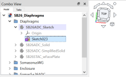
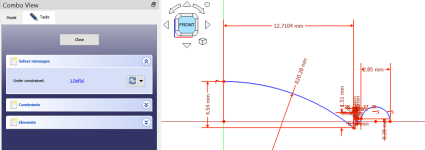
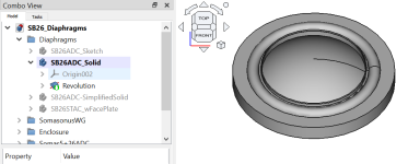
Source.Contours revolves your points/arcs/lines into a surface starting from the center out. A little like the following image except FreeCAD forces you to turn a revolve into a solid instead of allowing a surface like ATH. I'm including the FreeCAD revolve so it's easier to see how to use the sketch in ATH. IMO, the "SimplifiedSolid" available in the FreeCAD navigation tree is better for simulation because it doesn't have all the fine details. For simulation I'd use the simplified model or make the simplified model even more simple than it is depending on how fine you make your tweeter mesh. And I just realized I used the detailed diaphragm in the FreeCAD waveguide example instead of the simplified diaphragm. So don't use it unless you enjoy punishing yourself. Instead, do the same type of boolean cut in the FreeCAD example file but use the simplified diaphragm rather than the detailed model.
The full and quarter enclosure models are for AKABAK. The Quarter Enclosure is for simulating in AKABAK using XY Symmetry, similar to defining "Mesh.Quadrants = 1;" in ATH. You can export it and add a 2D mesh to the surface using Gmsh. Which is a pain and will make you grateful for the ease of ATH automatically converting Source.Contours into Gmsh surfaces for you. I'd recommend using ATH for as much of your simulation as possible before reaching for AKABAK because the 2D surface meshing process is a PITA. If you can make your simulation in ATH/ABEC rather than AKABAK it will save you a ton of time by automating many tedious steps involved in sizing your 2D meshes in addition to constructing a 2D mesh that will work reliably in ABEC. However, if you want to simulate your ATH waveguide on a cabinet you can't define in ATH you can use the longer CAD to AKABAK route. Also, AKABAK is a form based version of ABEC. If you read through your ATH generated text files for ABEC simulations you'll see that you're entering the same information into AKABAK's graphical user interface. Except, ATH always gets it right and my AKABAK simulations frequently fail due to human error.
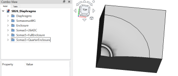
I also included a Somasonus 5 inch waveguide in the file so you can see how to re-construct one for AKABAK simulation because I had a heck of a time trying to figure out how to do it and maybe I can make it easier on someone else. In general, you sketch curves of the X&Y profiles then draw a series of ellipses elevated on the Z axis then use Additive Loft in the Part Design Workbench (specific to FreeCAD, not Fusion360) to turn it into a solid. Then you can take the solid and boolean cut either the SB26ADC or STAC diaphragms from the bottom of the Somasonus 5, then take that and cut it out of an enclosure. Once you have an enclosure with the waveguide/diaphragm cut out of the surface you can export it for Gmsh 2D surfacing and finally AKABAK simulation. I included examples of the waveguide after cutting out a diaphragm and also cutting the waveguide/diaphragm combo out of an enclosure. The 1/4 enclosure allows you to simulate in AKABAK using XY Symmetry (similar to defining Mesh.Quadrants in ATH).
If you're new to FreeCAD the keyboard spacebar is used to toggle visibility. You can select the models in the folders then hide or show them by pressing your spacebar.
The diaphragm sketches can help you with Source.Contours


Source.Contours revolves your points/arcs/lines into a surface starting from the center out. A little like the following image except FreeCAD forces you to turn a revolve into a solid instead of allowing a surface like ATH. I'm including the FreeCAD revolve so it's easier to see how to use the sketch in ATH. IMO, the "SimplifiedSolid" available in the FreeCAD navigation tree is better for simulation because it doesn't have all the fine details. For simulation I'd use the simplified model or make the simplified model even more simple than it is depending on how fine you make your tweeter mesh. And I just realized I used the detailed diaphragm in the FreeCAD waveguide example instead of the simplified diaphragm. So don't use it unless you enjoy punishing yourself. Instead, do the same type of boolean cut in the FreeCAD example file but use the simplified diaphragm rather than the detailed model.

The full and quarter enclosure models are for AKABAK. The Quarter Enclosure is for simulating in AKABAK using XY Symmetry, similar to defining "Mesh.Quadrants = 1;" in ATH. You can export it and add a 2D mesh to the surface using Gmsh. Which is a pain and will make you grateful for the ease of ATH automatically converting Source.Contours into Gmsh surfaces for you. I'd recommend using ATH for as much of your simulation as possible before reaching for AKABAK because the 2D surface meshing process is a PITA. If you can make your simulation in ATH/ABEC rather than AKABAK it will save you a ton of time by automating many tedious steps involved in sizing your 2D meshes in addition to constructing a 2D mesh that will work reliably in ABEC. However, if you want to simulate your ATH waveguide on a cabinet you can't define in ATH you can use the longer CAD to AKABAK route. Also, AKABAK is a form based version of ABEC. If you read through your ATH generated text files for ABEC simulations you'll see that you're entering the same information into AKABAK's graphical user interface. Except, ATH always gets it right and my AKABAK simulations frequently fail due to human error.

Attachments
Last edited:
It's a curvature along the waveguide curve, but it's not easy to visually connect the two together, as it's not even linear.Please enlighten me 🙏.
This might be more intuitive: https://www.desmos.com/calculator/33u5tsf7dd
Here the curvature is the distance between the wg curve (black) and the red curve, along the normal to the black curve:
The thin violet curve is the corresponding rate of change of curvature and it's there just for fun 😉
Here is a grid export configuration to FreeCAD for an axisymmetric horn. It will only work for horns that have a single rotated profile => horns that can be simulated using circular symmetry ABEC.SimProfile = 0. A profile range of 0,0 is just one line of points. If you had a complex shape like the Tritonia you'd need to do a lot more work to get it into FreeCAD. In that case you might consider using Fusion 360 and use the ATH scripts to loft the Tritonia automatically then export a STEP from Fusion 360 to import into FreeCAD.
The attached zip file includes a FreeCAD example and the ASC file created by ATH through the GridExport function.
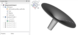
I included steps to import the ASC file into FreeCAD and revolve a horn. It isn't intended as a tutorial. It's just to give you an overview of how the attached FreeCAD file was made. Otherwise the workflow order of how I did it wouldn't be clear.
1) Use the Import Points tool from the Points Workbench to import the ATH grid export file. Optional: increase the point size to make them easier to see by selecting the imported point object then navigate to the properties panel (usually lower left of the screen) and select the View Tab => Object Style/Point Size. I increase point size to 10 so they're gigantic and easy to select.

2) Use the tools in the Draft Workbench to trace the waveguide profile points. For a curved profile you will probably use the b-spline tool. If you have a straight conical section in front of your horn you would probably use the line tool for that portion. When you hover over a point in your tool (b-spline) it will show the snap-to icon so you know you are snapping the spline to the profile point, then continue on to the next point. If you need to use multiple tools to trace your profile you have the option to join the separate lines using the JoinCurves tool in the Curves Workbench. It isn't necessary but I joined the curves in the attached FreeCAD file so you'll see it in there.


Optional: Join Curves tool in the Curves Workbench. The advantage is you can apply constraints to a single line rather than each separate line. You wouldn't need it if you only used one tool to trace your waveguide profile such as the b-spline too.
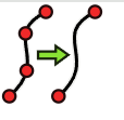
3) After you create your draft lines use the Draft to Sketch tool to convert your profile into a sketch. Why do you need to convert it into a sketch? Because sketches can be revolved around an axis to turn your profile into a three dimensional horn but draft lines can't.

4) Use the Part Design Workbench and add a Part Design Body to your model. This will act as a container for your profile sketch so you can revolve it around an axis the way ATH Source.Contours revolves around the Z-axis.
Click the Create Body tool too add the Body to your model. Drag your profile sketch created in step 3 to the Part Design Body.
After you make the modifications you want to your profile sketch you will probably use the Part Design Revolve tool to turn it into a solid shape axisymmetric horn. But there's a lot of CAD design work involved if you're trying to design 3D models like Marcel has on his website. If you're just trying to create a basic surface model for simulation (not a lot of detail, surface only, no part thicknesses that need to fit each other) it is a little less work. FreeCAD won't allow you to revolve a sketch that isn't "closed" because the revolution is creating a solid. If you import the ATH profile and try to revolve a sketch before closing the lines it will fail and complain. I included four different profile revolutions to show a few ways you could close the sketch before revolving but these aren't the only options. And you don't need to revolve the sketch in a full 360 degrees. For example, you could revolve it 90 degrees if you only wanted a quartered section of a horn to simulate with AKABAK's XY Symmetry option.

GridExport:cadProfile = {
ProfileRange = 0,0 ; Exports a single profile
;SliceRange = <from>,<to>
ExportProfiles = 1
ExportSlices = 0
Scale = 1.0
Delimiter = " " ; use a space delimiter for FreeCAD using the Points Workbench and the Import Points tool
FileExtension = "asc" ; use the asc file type for FreeCAD
;SeparateFiles = 0|1
}
The attached zip file includes a FreeCAD example and the ASC file created by ATH through the GridExport function.

I included steps to import the ASC file into FreeCAD and revolve a horn. It isn't intended as a tutorial. It's just to give you an overview of how the attached FreeCAD file was made. Otherwise the workflow order of how I did it wouldn't be clear.
1) Use the Import Points tool from the Points Workbench to import the ATH grid export file. Optional: increase the point size to make them easier to see by selecting the imported point object then navigate to the properties panel (usually lower left of the screen) and select the View Tab => Object Style/Point Size. I increase point size to 10 so they're gigantic and easy to select.

2) Use the tools in the Draft Workbench to trace the waveguide profile points. For a curved profile you will probably use the b-spline tool. If you have a straight conical section in front of your horn you would probably use the line tool for that portion. When you hover over a point in your tool (b-spline) it will show the snap-to icon so you know you are snapping the spline to the profile point, then continue on to the next point. If you need to use multiple tools to trace your profile you have the option to join the separate lines using the JoinCurves tool in the Curves Workbench. It isn't necessary but I joined the curves in the attached FreeCAD file so you'll see it in there.


Optional: Join Curves tool in the Curves Workbench. The advantage is you can apply constraints to a single line rather than each separate line. You wouldn't need it if you only used one tool to trace your waveguide profile such as the b-spline too.

3) After you create your draft lines use the Draft to Sketch tool to convert your profile into a sketch. Why do you need to convert it into a sketch? Because sketches can be revolved around an axis to turn your profile into a three dimensional horn but draft lines can't.

4) Use the Part Design Workbench and add a Part Design Body to your model. This will act as a container for your profile sketch so you can revolve it around an axis the way ATH Source.Contours revolves around the Z-axis.
Click the Create Body tool too add the Body to your model. Drag your profile sketch created in step 3 to the Part Design Body.

After you make the modifications you want to your profile sketch you will probably use the Part Design Revolve tool to turn it into a solid shape axisymmetric horn. But there's a lot of CAD design work involved if you're trying to design 3D models like Marcel has on his website. If you're just trying to create a basic surface model for simulation (not a lot of detail, surface only, no part thicknesses that need to fit each other) it is a little less work. FreeCAD won't allow you to revolve a sketch that isn't "closed" because the revolution is creating a solid. If you import the ATH profile and try to revolve a sketch before closing the lines it will fail and complain. I included four different profile revolutions to show a few ways you could close the sketch before revolving but these aren't the only options. And you don't need to revolve the sketch in a full 360 degrees. For example, you could revolve it 90 degrees if you only wanted a quartered section of a horn to simulate with AKABAK's XY Symmetry option.

Attachments
Last edited:
There's also the Convert operation in the Form (T-Spline) workbench in Fusion that can convert a quad mesh into a T-Spline body, which then becomes a BRep body. By body I mean volume or also surface, I think, haven't checked now. I know there's also the SurfaceImport script that comes with ATH, haven't checked it either.
Could be a simplistic manual way to import a complex shaped quad mesh from ATH (or something else), but at the extreme edges of throat and mouth the Crease operation would have to be applied manually. (Like imagine importing a quad mesh of a hexagonal tube. Importing it results in a smooth blob, applying Crease at the extremes results in cylinder with a circular wall. I guess for a WG the error would be low with a reasonably fine mesh.)
Could be a simplistic manual way to import a complex shaped quad mesh from ATH (or something else), but at the extreme edges of throat and mouth the Crease operation would have to be applied manually. (Like imagine importing a quad mesh of a hexagonal tube. Importing it results in a smooth blob, applying Crease at the extremes results in cylinder with a circular wall. I guess for a WG the error would be low with a reasonably fine mesh.)
Last edited:
By the way here's some discussion from earlier in this thread about drive values for the surround:
As for simulating dome tweeters, ABEC allows to define different weights to different driving elements. This is what I did - I set a lower weight for the surround. In this case the surround is divided into two rings of weights 0.75 and 0.25 respectively. Maybe one ring at 0.5 would be sufficient, I don't know, could be checked. The weights are set in the script file, along with the whole dome geometry, or whatever it is.
This will also be part of the 4.6 release, which will be really a major update. I still need to finish the documentation...
This will also be part of the 4.6 release, which will be really a major update. I still need to finish the documentation...
So I've been thinking a bit about the weighting of the driving elements in this simulation. Namely, how they relate to Sd, the "effective piston area" of the driver.
Using bidland's recent project as an example, if you multiply the area of each of the driving elements by it's weight constant (from the demo ath scripts) the result is larger than the listed Sd, implying that the simulation doesn't quite match the tweeter.
I did a bit of algebra and came up with the attached equations for determining the weight of both driving elements in the surround based on the geometry and the Sd from...
I believe the weights 0.75 and 0.25 are pretty much correct. The task is to determine the relative excursions of the blue rings depicted below, so that their volume displacements are the same as of the actual corresponding parts of the surround. If you do the calculation, you'll notice it's just a tiny bit different (depending on the actual dimensions of the surround), but the error is on the order of 1 - 2%. But given how crude is the whole model, this has just a marginal importance, IMO.

Last edited:
I managed to screw up my ATH install by screwing around with AKABAK+Gmsh. I don't have a solution yet but if I can figure it out I'll post it in case anyone else runs into it too.
Problem: when using ATH 4.9.0.xxx (I have three legacy versions plus the most recent) I get the following error message in the command window
Consequence of the error is ATH doesn't generate the ABEC project file. However, my ATH 4.8.x, 4.7.x, and 4.6.x versions still work. I deleted and re-installed Gmsh 4.6.0 just in case I corrupted it while using AKABAK but that didn't solve the problem. I also deleted and reinstalled ATH 4.9.0-231015 from my zip file archive. No joy. I can manually open Gmsh 4.6.0 from the command prompt but it looks like my operating system is blocking ATH 4.9.0 from opening Gmsh, regardless of Gmsh version.
Just realized I haven't tried uninstalling ABEC and AKABAK yet. I'll give that a shot now and report after a reboot.
Problem: when using ATH 4.9.0.xxx (I have three legacy versions plus the most recent) I get the following error message in the command window
Info : Started on Sat Dec 14 15:52:21 2024
Info : Reading 'bem_mesh.geo'...
error: gmsh call status = 1
Consequence of the error is ATH doesn't generate the ABEC project file. However, my ATH 4.8.x, 4.7.x, and 4.6.x versions still work. I deleted and re-installed Gmsh 4.6.0 just in case I corrupted it while using AKABAK but that didn't solve the problem. I also deleted and reinstalled ATH 4.9.0-231015 from my zip file archive. No joy. I can manually open Gmsh 4.6.0 from the command prompt but it looks like my operating system is blocking ATH 4.9.0 from opening Gmsh, regardless of Gmsh version.
Just realized I haven't tried uninstalling ABEC and AKABAK yet. I'll give that a shot now and report after a reboot.
Uninstalling ABEC and AKABAK did not work. However, a reinstalled version of ABEC3 was unable to process any ATH scripts without ABEC complaining about script errors so I decided to pull the ripcord and recover a Windows backup before I screwed things up with AKABAK+Gmsh.
Now that I have a clean machine I'll install AKABAK again and see if that was what caused the error I experience in post 16,370. If that's not the cause then it was something I did with Gmsh. Sorry I don't have an answer for this.
Now that I have a clean machine I'll install AKABAK again and see if that was what caused the error I experience in post 16,370. If that's not the cause then it was something I did with Gmsh. Sorry I don't have an answer for this.
For those waiting I've just published the long adapter for BMS 4554: https://www.at-horns.eu/gen2-4554.html
I'll add more material as time goes...
I'll add more material as time goes...
Hi mabat
my 4554s waited for them ;-)
But this week busy and then on vacation 😨. So have to wait a bit.
Still I think about best LF extension for a ATH project. What about adding some 4-5" LF drivers as MEH with XO @700Hz to the 4554 in a 460 or 520? 1/4 Distance with that XO frequeny seems pretty easy...
...and much more simple than my thoughts on modding a dcx464...
If I knew better I would do it 🙂
This is currently my top design and honestly, I'm not seeing changing that any time soon.

There's certainly still space for injecting even a lower-frequency signal somewhere along the adapter, but I think I'm going to leave that for others to try.
This is currently my top design and honestly, I'm not seeing changing that any time soon.
There's certainly still space for injecting even a lower-frequency signal somewhere along the adapter, but I think I'm going to leave that for others to try.
Last edited:
Within the adapter I fear a lot influence on HF dispersion. But with 12cm for lamda/4 and such a slowly expanding throat it ends up within the adapter 🤔🤷♂️
You must be thinking of the "Horn Flower" reversed "MEH"... ;-)What about adding some 4-5" LF drivers as
So this isn't (for a change) an assault for the ultimate reproduction quality (all mine failed so far 🙂) but I hope for maybe at least one or two extraordinary sound properties and a look that befits a small but cool penthouse flat.
It will try to be as much of a point source as possible but has no prospect of having a truly flat, linear, directivity - it wont. The aim is for it to be really high resolving and low distorsion (if not pushed) - SPL to reach 70/90 dB (crest/peak).
Due to space constraints it need to occupy little floor space and rest close to wall. Most often only one...
I'll soon will publish a thread about the sequel... "Big Flower"... 🙂
//
Teaser...

Horn part is a slight modified ATH A520G2, for the SB ROSSI 1,4", made out of concrete, as is the "basket" with room for 6 pcs of 5,5" SB woofers. In the picture not yet assembled, horn just leans towards the basket.
//
Horn part is a slight modified ATH A520G2, for the SB ROSSI 1,4", made out of concrete, as is the "basket" with room for 6 pcs of 5,5" SB woofers. In the picture not yet assembled, horn just leans towards the basket.
//
Wow!made out of concrete
I'm very much looking forward to see production photos!
Any recommendations for another BMS driver that it would be worth making a long adapter for, in the same way as for the 4554?
I went through their catalogue and the differences between the drivers are not always quite clear to me. Which one to try next?
I went through their catalogue and the differences between the drivers are not always quite clear to me. Which one to try next?
- Home
- Loudspeakers
- Multi-Way
- Acoustic Horn Design – The Easy Way (Ath4)