Thanks for taking the time to share your process. I really think something like this should be a sticky somewhere. 🙂OK I am:
1. Generating profile in ATH4, getting that into solidworks as a line of points (but its probably easier to just import the model now I think?
2. tracing that curve with a bezier, and filling out the rear of the horn
3. revolving that shape to give me the basic driver
I'm being general here, since I think theirs heaps of ways to do this stuff and lots of examples & videos hanging around
4. model now looks something like this and at this point I could add more geometry for holes, chambers etc etc. I'd also try adding geometry here for interfaces or whatever, but I think they could also be added in gmsh (but I didn't need them for the above examples
View attachment 1286644
5.export as STEP
6. In GMSH follow steps similar to the video above, but here are some extra tips;
- in tools-> options ->mesh: I used these settings, as well as setting "Compute element sizes from curvature" in advanced. this all seemed to give me a fine enough mesh for ~8khz
View attachment 1286646
- You need to add surfaces like he does in the video, but you can get away with just 2 surfaces, the driving element, and the horn itself.
- When selecting the faces for the surfaces, DONT include the sides which are where the symmetry completes the horn. When you import into akabak the edges should be 'missing' shown in my prev post.
- after alll the changes have been made, click "reload script" then press "2D" and the meshing will happen. now you should have a result like this
View attachment 1286653
7. Now export like he does in the video
8. To make your life easy, import a complete freestanding ATH4 project into AKABAK, this sets up most of the settings you need, the observation scripts etc. just make sure it had no interfaces etc specced. so then its just a simple one, or just follow the guys video above, its only a few min to setup
9. Open mesh file like in the video, General -> Mesh File ->File-> open/reopen button
10. set scaling to 1mm
11. in Drawing, import all, inspect the mesh for holes or whatever. make sure the edges arn't fillled in
View attachment 1286656
12. in BEM tab, set the corresponding mesh lables for each element entry. make sure the correct one is set to driving etc
View attachment 1286658
13. Manually run meshing, check for errors/warnings which might mean the mesh sizes are not correct, or some other issue
14. goto Global -> Fixed Driving, and enable
15. run processing -> calculate all
16. assuming it runs, you should get something in VACS now. you can actually edit/add observations, and then recalc just the observations/fields in the processing menu, and rerun/revisualise that without running the whole thing again, which is nice cos its INSANELY slow with a complex mesh.
17. some crappy meshes might run, but converge really slowly, not sure why. sometimes more elements is faster?
hopefully between this and other videos, its enough breadcrumbs

I find it interesting that all you are using ATH for is generating the original geometry. I was trying to use the generated ABEC projects in both ABEC3 and AKABAK and generally failing. even trying to import the meshes I was running into many issues in GMSH (various versions). The method you use seems to sidestep these issues.
I am interested in how you add the driving element, you mention this in 2 and 3, do you just add a disc here? Do you add a rear chamber like in the video?
I am interested in how you add the driving element, you mention this in 2 and 3, do you just add a disc here? Do you add a rear chamber like in the video?
Ha yeah, ok in this case, I just literally used the rear face of the horn, which is created in the revolution. obviously thats a perfect flat driving case, but I think thats good enough for what i'm trying to do here. below shows me just selecting that face and giving it the surface group so it can be selected in akabak

Hi Psytron and Drofdissonance,
Great to see more people using Solidworks! In another thread I showed how to create an ATH curve within SW.
It was just some rewritting the original formulas, but it worked! You will have to use equation driven curve within a sketch and global equation variables.
Here the link with the X(t) and Y(t) formulas:
Solidworks ATH forumula's
Hope it helps with the workflow!
Not yet as I'm still occupied by printing and assembling. Only after that I will run the measurements.@mabat - just curious if this was ever tested?
BTW, today I printed petals for the EXAR550 (#14,466), it has 10 segments. With a very sparse infill and one perimeter only, each petal is only 85 grams and surprisingly well damped. I also used some Kingroon PLA this time - it's as good as the Sunlu META.
It seems that the thick petal structure with sparse infill is not a bad thing. Very light and almost ringing-free so far. Let's see when assembled. I also use a PU glue now and I like it much better than any CA or epoxy used previously.
Hi Bobbit, I'm not using solid works, just a similar way of generating the mesh for AKABAK. Thanks for the link to your formula. I am currently writing my own in python, I would rather code than CAD where I can. 🙂Hi Psytron and Drofdissonance,
Great to see more people using Solidworks! In another thread I showed how to create an ATH curve within SW.
It was just some rewritting the original formulas, but it worked! You will have to use equation driven curve within a sketch and global equation variables.
Here the link with the X(t) and Y(t) formulas:
Solidworks ATH forumula's
Hope it helps with the workflow!
I used it once to stick two plates of a large gear pulley together. It forms a strong bond but be careful, a little goes a long way because it doesn't soak in, and it can be quite messy to clean up a spill of it. It is a moisture cure glue so a little spritz of water on one piece helps it go off quicker.
I've had pretty good luck gluing PLA with methylene chloride. It dissolves and welds the PLA together, like plumbing glues for PVC and ABS
"Methylene chloride (CH2Cl2) is a colorless liquid that can harm the eyes, skin, liver, and heart. Exposure can cause drowsiness, dizziness, numbness and tingling limbs, and nausea. It may cause cancer. Severe exposure can cause loss of consciousness and death."
+
"EPA identified risks for adverse human health effects, including neurotoxicity, liver effects, and cancer from inhalation and dermal exposures to methylene chloride."
be safe...
//
+
"EPA identified risks for adverse human health effects, including neurotoxicity, liver effects, and cancer from inhalation and dermal exposures to methylene chloride."
be safe...
//
PLA, especially blends designed for ease of printing tend to distort over time when under pressure/loading even in cool climates, in hot climates it is pretty much useless except for printing one-offs and objects that do not have forces applied over long periods(like moulds). I do all my speaker work in ABS if it isn't a one-off prototype. Heat-set inserts are magic for larger parts, between these and some keying between parts anything is possible!
It's a pretty standard glue for plastics. You can find it at hobby shops under the name "Plastruct plastic weld". My local plastic store sells it for gluing up acrylic and polycarbonate sheet assemblies. Needle tip bottles work nicely for dispensing it. It was also the main solvent in older paint strippers. Just take the usual precautions like with any other aggressive solvents. You'd only need a few mL to glue up one of these waveguides.
What I use now is basically this one: https://www.soudal.co.uk/pro/products/adhesives/timber-adhesives/pro-45p-fast-pu-wood-adh
I just have it from a different company I guess, in a smaller package, as very little is needed: https://profimodel.cz/en/ostatni/16441-purex-rapid-pro45p-100g-polyuretan-lepidlo-8595241336237.html
It's the most easy one to use from what I have tried.
I just have it from a different company I guess, in a smaller package, as very little is needed: https://profimodel.cz/en/ostatni/16441-purex-rapid-pro45p-100g-polyuretan-lepidlo-8595241336237.html
It's the most easy one to use from what I have tried.
Hi Bobbit, I'm not using solid works, just a similar way of generating the mesh for AKABAK. Thanks for the link to your formula. I am currently writing my own in python, I would rather code than CAD where I can. 🙂
Nice! Here's a notebook with the R-OSSE equations in python if you did not find the time for it yet. What python CAD library are you going to use?
https://github.com/additaudio/rosse/blob/main/rosse-notebook.ipynb
Thanks speetpeet. 🙂 So far I have just used numpy for the calcs and plotly to see what I am doing. Will be using gmsh for meshing and investigating bempp for BEM. Currently only have implemented OSSE. I do have it rotated around into 3d and a pretty graph tho. 🙂
Reach out/fork and make a pull request if you want to collab.
Current best entry point for my code is the develop branch (linked) and "axis_symmetric.py"
Github PythonHornDesign

Reach out/fork and make a pull request if you want to collab.
Current best entry point for my code is the develop branch (linked) and "axis_symmetric.py"
Github PythonHornDesign
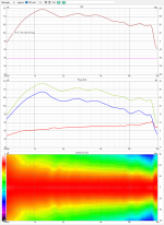
If its of any value - here are my measurements of the ATH280EX-MK2 with the Peerless DFM-2535. My print was far from perfect and the measurement setup was quick. All measurements - approximately 4.2ms gate time. These are pretty good results, no?Not yet as I'm still occupied by printing and assembling. Only after that I will run the measurements.
Here is normalized for 10 degress.
Attachments
Last edited:
HORRENDOUS, Far too many lines.
no its gorgeous. 66$ driver and this looks cleaner than genelec ones!
how is the distortion down low? be really awesome to see how low you think it would play, at a high level 105-110dB max I guess? judging by the DI, it would be possible to get the horn down to 700-800 hz, but how is the driver down there?
Thanks, I'm pleased by the results, it really cheered me up.
As for the throat extension, it reduces the excursion on the lower end considerably. At 800 Hz it must be completely fine here, IMHO.
Maybe even a longer extension would be beneficial, it's still hard to predict. With the cylindrical throat of the 280EX it's not difficult to try though.
BTW, this just begs for a semi-open/cardioid midrange.
Last edited:
- Home
- Loudspeakers
- Multi-Way
- Acoustic Horn Design – The Easy Way (Ath4)