yes you are right this one is just probably zero angle with naked pahse plug and with adapter from 1,4" to 2" so one model sold with two different throats like Radian 950. Good for ESP lens evaluation.
Last edited:
Unfortunately a "naked" phase plug (i.e. with a short or no exit section) doesn't mean it's coherent enough for an ESP to work properly. If it's not, it would need a wavefront "averager/coherer" inserted before the ESP - it could be a duct with vanes/fins as shown above. This is perhaps still worth a try.
- This is the idea. And of course I will try some vanes in the throat, now that we see what it can do...


The ability to segment the horns like that is extremely nice for both construction and cosmetic reasons. I had a h*ll of a time trying to print axisymmetric waveguides: plastic warping failures, trying to get breaks to line up, etc.
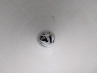
I'm such an idiot. Haha, very embarrassing mistake.This appears almost as the Mercedes Benz logo. In the peace sign the vertical bar would have to continue across the whole diameter ☮.
Yea, and I still wonder about the best material. Could be flexi plywood, sheet metal or even (laminated) paper. I'd like metal, aluminum or brass, but need to try what thickness I'm still able to bend without too much struggle...The ability to segment the horns like that is extremely nice for both construction and cosmetic reasons.
I already have the petal template:
Thin MDF would be my guess. It could be CNC routed/milled for the overall shape, and also have internal alignment slots cut in that match up with a backup shaping guide (you bend the petal onto the curve of the backup shaping guide and the mortises/slots help keep the petal aligned during fit-up).Yea, and I still wonder about the best material. Could be flexi plywood, sheet metal or even (laminated) paper. I'd like metal, aluminum or brass, but need to try what thickness I'm still able to bend without too much struggle...
I already have the petal template:
View attachment 1184065
Do the fins/veins need to exist across the entire wavefront? E.g. is the effectiveness seen more at the waveguide wall or in the center?
And could this be use to partially overcome the fin density issue blocking up the throat, with more 'finage' in the centre or side wall?
And could this be use to partially overcome the fin density issue blocking up the throat, with more 'finage' in the centre or side wall?
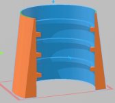
PR: Duct with 3 outer rings
PM: Failed 3D print of the PR
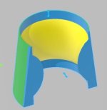
PB: Bump in center reducing duct from 18mm to 13 mm.
First PR print failed and made a spider web mess inside the duct so I decided to measure it.


PM: Failed 3D print of the PR
PB: Bump in center reducing duct from 18mm to 13 mm.
First PR print failed and made a spider web mess inside the duct so I decided to measure it.
Attachments
Now it would be interesting to see the bump (PB) + vanes.
- If you published the exact dimensions of the plug shell you use, I would also send you some STLs to try, as you already have it all ready 🙂
- If you published the exact dimensions of the plug shell you use, I would also send you some STLs to try, as you already have it all ready 🙂
Don't they form a phase plug? In relation to surface, the fins occlude much more space in the center and increase the path length.Do the fins/veins need to exist across the entire wavefront? E.g. is the effectiveness seen more at the waveguide wall or in the center?
And could this be use to partially overcome the fin density issue blocking up the throat, with more 'finage' in the centre or side wall?
Think of the fins as paper-thin. That would represent their primary effect. The thickness will have an efect, probably mostly unwanted, but that should be only secondary. Of course it's better to add as few of them as necessary.
From what I gathered it's important to really divide the internal volume. Leaving them unconnected in the center would probably not work as good (my guess).
From what I gathered it's important to really divide the internal volume. Leaving them unconnected in the center would probably not work as good (my guess).
STL file and 3mf. 3mf includes an 18mm cylinder that can be subtracted from the shell to create the duct.Now it would be interesting to see the bump (PB) + vanes.
- If you published the exact dimensions of the plug shell you use, I would also send you some STLs to try, as you already have it all ready 🙂
Attachments
Although, you wouldn't need to worry about the shell unless you're interested in printing it for your own DE250. I can put an STL into the shell. Anything 18mm in diameter and no longer than 19.68mm long. It is 19.68mm long due to the 3D printer slicing at 0.12 mm resolution. It would change a little with different layer heights. But I can adjust for that.

Now a little bit off-topic but perhaps interesting. I'm putting together my measuring equipment and quickly tried the open baffle I'm working on, placed temporarily in my living room. I was curious so I compared it to a common-construction speaker, the Indiana Line DJ 310, both measured ~2m away at ~1m height, without any gating.
The black curve is the DJ 310, the blue and green curves are the OB (just the raw woofer) in a bit different position (distance from the wall, IIRC):


The black curve is the DJ 310, the blue and green curves are the OB (just the raw woofer) in a bit different position (distance from the wall, IIRC):
- Home
- Loudspeakers
- Multi-Way
- Acoustic Horn Design – The Easy Way (Ath4)