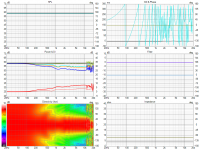
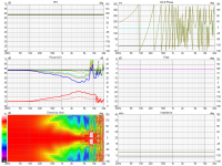
It's obvious now that the wide / non-narrowing vertical pattern of the BLD is kind of a trick (but a neat one) 🙂
Hah, yeah, better measure exactly right to catch the pattern 🙂
It is nice view of the device, I'm glad you added that. Might catch issues from that, like the BLD is probably fine waveguide you already pointed out the detail whicj wasn't visible on other data.
What does the top octave look like, for example 14kHz?
It is nice view of the device, I'm glad you added that. Might catch issues from that, like the BLD is probably fine waveguide you already pointed out the detail whicj wasn't visible on other data.
What does the top octave look like, for example 14kHz?
What is the correct entry for "PhaseComp = 2" when in ABEC's observations.txt?
After mabat's example from https://www.diyaudio.com/community/...-design-the-easy-way-ath4.338806/post-7169897 I had moved PhaseComp from within the FRDExport clause one level higher. But after a night of calculations, while I received a working set of polars in one export step (what a comfort), in VCad I have this weird interferences within the crossover region when both sources are enabled:
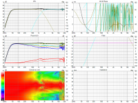
After mabat's example from https://www.diyaudio.com/community/...-design-the-easy-way-ath4.338806/post-7169897 I had moved PhaseComp from within the FRDExport clause one level higher. But after a night of calculations, while I received a working set of polars in one export step (what a comfort), in VCad I have this weird interferences within the crossover region when both sources are enabled:

Incredible functionality, mabat. Possible to insert the command into observations.txt after calculation? My last simulation run of 12 hours is still open in ABEC and I would love to have a peak at the field.
Today, we have received the new prices for electricity from January 2023, German market: at 0.48 Euro per kW/h, whith a 1 kW PC power supply, each full run will cost 6 Euros from next year 🤔
Today, we have received the new prices for electricity from January 2023, German market: at 0.48 Euro per kW/h, whith a 1 kW PC power supply, each full run will cost 6 Euros from next year 🤔
Last edited:
The phase is obviously greatly overcompensated. Perhaps the example I gave was not a good one or I forgot how it works (I don't use it myself). The phase compensation is automatically set to the mic distance by default, so you should set this (additive) value to zero in this case, I guess. By setting it to 2 you add another two meters traveling distance to the compensation....
You can easily add a planar field manually in observation.txt however, without the need to re-solve the project.
Unfortunately for the spherical field the mesh file needs to be re-generated (at least I don't know how to create such a surface in an ABEC script alone).Possible to insert the command into observations.txt after calculation?
You can easily add a planar field manually in observation.txt however, without the need to re-solve the project.
Last edited:
Parameter "PhaseComp" is not necessary anymore for unwrapping as it had been some versions ago if I understand correctly?
Well it has never been for unwrapping (that's something else), but for a compensation, i.e. removing the travel delay. It's for manual fine tuning of this compensation. The basic compensation is now automatic (=Distance) - perhaps this changed from the very first implementation, honestly I don't remember.
The Shell command is what you want for that, AKABAK has a Shell Field creation tool, in ABEC it's under the BE Script so would still likely have to be resolved.(at least I don't know how to create such a surface in an ABEC script alone).
The corrupted phase issue remained after another simulation run:
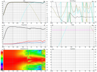
Sometimes solving of fields fails:
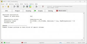
When I removed one entry from observations.txt, non-normalized plot "PM_SPL", it solved. ath49 sometimes was terminated after generating FRD from this. In the FRD files, only first normalized file had numerical phase enty, other files -inf. Afterwards adding "PM_SPL" again, also solved with unmodified observations.txt:
waveguide.cfg has the following setup:
Any hints what could be causing the issue appreciated.

Sometimes solving of fields fails:

When I removed one entry from observations.txt, non-normalized plot "PM_SPL", it solved. ath49 sometimes was terminated after generating FRD from this. In the FRD files, only first normalized file had numerical phase enty, other files -inf. Afterwards adding "PM_SPL" again, also solved with unmodified observations.txt:
Code:
Driving_Values
  DrvType=Acceleration; Value=1.0
  401  DrvGroup=1001  Weight=1 Delay=0.0
  402  DrvGroup=1002  Weight=1 Delay=0.0

Radiation_Impedance
  BodeType=Complex; GraphHeader="RadImp"
  Range_min=0; Range_max=2; RadImpType=Normalized
  403   1001 1001   ID=8001
  404   1002 1002   ID=8002

BE_Spectrum
  PlotType=Polar; GraphHeader="PM_SPL"
  BodeType=LeveldB; Range_max=5; Range_min=-45
  PolarRange=0,180,72
  BasePlane=zx
  Distance=2m
  501  Inclination=0  DrvGroups=1001  ID=5001


BE_Spectrum
  PlotType=Polar; GraphHeader="PM_SPL_H_T"
  BodeType=LeveldB; Range_max=5; Range_min=-45
  PolarRange=-180,180,72
  BasePlane=zx
  Distance=2m
  NormalizingAngle=0
  502  Inclination=0  DrvGroups=1001  ID=5002


BE_Spectrum
  PlotType=Polar; GraphHeader="PM_SPL_H_W"
  BodeType=LeveldB; Range_max=5; Range_min=-45
  PolarRange=-180,180,72
  BasePlane=zx
  Distance=2m
  NormalizingAngle=0
  503  Inclination=0  DrvGroups=1002  ID=5003


BE_Spectrum
  PlotType=Polar; GraphHeader="PM_SPL_V_T"
  BodeType=LeveldB; Range_max=5; Range_min=-45
  PolarRange=-180,180,72
  BasePlane=zx
  Distance=2m
  NormalizingAngle=0
  504  Inclination=270  DrvGroups=1001  ID=5004


BE_Spectrum
  PlotType=Polar; GraphHeader="PM_SPL_V_W"
  BodeType=LeveldB; Range_max=5; Range_min=-45
  PolarRange=-180,180,72
  BasePlane=zx
  Distance=2m
  NormalizingAngle=0
  505  Inclination=270  DrvGroups=1002  ID=5005
waveguide.cfg has the following setup:
Code:
; ____ Source Mode ____

Source.Shape = 1
Source.Curv = 0
Source.Radius = -1
Source.Velocity = 1

; ____ Enclosure ____

Mesh.Enclosure = {
Spacing = 27,30,27,367 ; edge distances (left,top,right,bottom)
Depth = 270
EdgeRadius = 25
EdgeType = 1
FrontResolution = 10,10,20,20
BackResolution = 20,20,30,30

LFSource.B = {
    Spacing = 70
    Radius = 106.5
    DrivingWeight = 1.0
    SID = 1
 }
}

; ____ LE Model ____

LE = generic25

; ____ 3D Mesh Settings ____

Mesh.LengthSegments = 20
Mesh.AngularSegments = 64
Mesh.ThroatResolution = 2
Mesh.MouthResolution = 8.0
Mesh.SubdomainSlices =

Mesh.ZMapPoints = 0.5,0.1,0.76,0.733
Mesh.Quadrants = 14

; ____ Measurement Axis ____

Mesh.VerticalOffset = 126.5

; ____ ABEC Settings ____

ABEC.MeshFrequency = 1000
ABEC.NumFrequencies = 30
ABEC.SimType = 2
ABEC.f1 = 20
ABEC.f2 = 20000

; ____ VCAS Output ____


ABEC.Polars:SPL = {
  MapAngleRange = 0,180,72
  Distance = 2.0
 }

ABEC.SphericalField:1 = {
Radius = 0.8
; Angle = 90
; Density = 30
}

ABEC.Polars:SPL_H_T = {
  SID = 0
  MapAngleRange = -180,180,72
  Distance = 2
  NormAngle = 0

    FRDExport = {
    NamePrefix = hor_tweeter
  }
}


ABEC.Polars:SPL_V_T = {
  SID = 0
  MapAngleRange = -180,180,72
  Distance = 2
  Inclination = 270
  NormAngle = 0

    FRDExport = {
    NamePrefix = ver_tweeter
  }
}

ABEC.Polars:SPL_H_W = {
  SID = 1
  MapAngleRange = -180,180,72
  Distance = 2
  NormAngle = 0

    FRDExport = {
    NamePrefix = hor_woofer
  }
}


ABEC.Polars:SPL_V_W = {
  SID = 1
  MapAngleRange = -180,180,72
  Distance = 2
  NormAngle = 0
  Inclination = 270

    FRDExport = {
    NamePrefix = ver_woofer
  }
}
Any hints what could be causing the issue appreciated.
I'm not sure it has any value, as it's strongly dependent on a particular driver above ~13k, as we saw already.What does the top octave look like, for example 14kHz?
Reason for above phase problem could be: Copied the folders doc, export, lib from ath483beta in the 49 prerelease, ran -r command again from same data, issue gone. Sadly did not save Spectrum_ABEX.txt from the higher resolution run, but low resolution data now without the phase issue.
Quickly checked if fields would reveal any surprises, but this waveguide does what was expected from x- and y-axis graphs:
vertically wide low, for better crossover power; extra energy in vertical HF as a trick to have enough energy up top while also having horizontal pattern as smooth as possible, in-between asymmetrical.
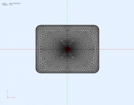
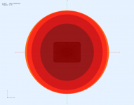
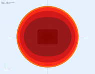
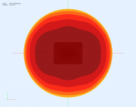
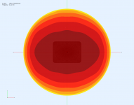
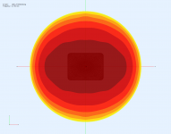
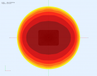
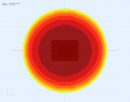
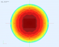
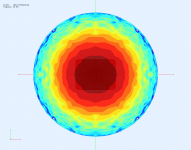
vertically wide low, for better crossover power; extra energy in vertical HF as a trick to have enough energy up top while also having horizontal pattern as smooth as possible, in-between asymmetrical.


I saw from the current implementation of this field that the shell is kind of bound to the (one) source, and as soon as half symmetry is defined (with second source), only the upper hemisphere remains. Is it possible to generate such a shell that sees the field for two combined sources?
I'm probably missing something real obvious, but I followed the tutorial can't seem to get gmesh to be recognized doing the tutorial in the help file.
When I run the ">ath demos\demo1.cfg", I can only get to "Calculating profiles" and the mesh.geo is the only file created in the OutputRootDir. I can open the geo file and see the horn profile in Gmesh.
This is the output in CMD:
This is the config file for the help file tutorial:
This is the ATH config file:
When I run the ">ath demos\demo1.cfg", I can only get to "Calculating profiles" and the mesh.geo is the only file created in the OutputRootDir. I can open the geo file and see the horn profile in Gmesh.
This is the output in CMD:
Code:
D:\ATH\4.8.2>ath demos\demo1.cfg
Ath 4.8.2
-------------------------------------------------
   DIY version for personal non-commercial use
-------------------------------------------------
   Marcel Batik                  Czechia, 2022
   PayPal: mbatikp@atlas.cz
-------------------------------------------------

-destination directory: D:\ATH\Exported Horns\demo1
-initializing
-calculating profiles

D:\ATH\4.8.2>
This is the config file for the help file tutorial:
Code:
Throat.Profile = 1 ; 1 = OS-SE waveguide
Throat.Diameter = 25.4 ; [mm]
Throat.Angle = 7 ; half the included angle [deg]
Coverage.Angle = 45 ; half the included angle [deg]
Length = 100 ; [mm]
Term.s = 0.5
Term.n = 4.0
Term.q = 0.996
Morph.TargetShape = 0 ; 0 = no morphing (the default)
Mesh.AngularSegments = 64
Mesh.LengthSegments = 20
Mesh.ThroatResolution = 4.0 ; [mm]
Mesh.InterfaceResolution = 8.0 ; [mm]
Mesh.InterfaceOffset = 5.0 ; [mm]
Output.STL = 1
Output.ABECProject = 0
This is the ATH config file:
Code:
OutputRootDir = "D:\ATH\Exported Horns"
MeshCmd = "D:\ATH\gmsh-4.11.0-Windows64\gmsh.exe %f -"
GnuplotPath = "D:\ATH\gnuplot\bin\gnuplot.exe"- Home
- Loudspeakers
- Multi-Way
- Acoustic Horn Design – The Easy Way (Ath4)
