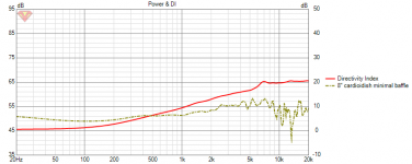
To remove possible confusion here is image with ideal 15" driver on minimal baffle vs. 8" cardioidish. DI lines intersect around 500Hz meaning that the 8" cardioid has lower DI above that, but greater below. Of course the 8" would need smaller waveguide as well and possibly higher crossover point, > 1kHz. This would mean that for example at 1kHz the system DI is lower than with 15". The cardioidish example here is my prototype and the DI could be tweaked some < 1kHz, but yeah cannot do nothing above that.
Red line is 15", dashed 8" cardioidish.
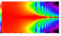
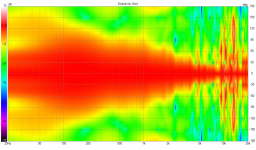
edit. added normalized polar maps for both
Red line is 15", dashed 8" cardioidish.
edit. added normalized polar maps for both
Attachments
Could you do the same but use 8" (i.e. a diaphragm corresponding to an 8" woofer) instead of 15" for the red curve?
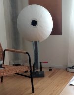
There is also possibility to "MTM" the cardioid part which makes flat DI system but it is narrow on vertical on the mids, wide on horizontal. Not sure if this sounds any better although reduced ceiling and floor interaction might be worth a try. These are easy to stack up and experiment with spacing. When the summer comes over I'll build another one, currently a mono setup. Saving up for 3D printer to make better waveguide 😀

^sure, wait a minute
^sure, wait a minute
Attachments
Last edited:

Here, red line is ideal 8" driver on minimal baffle.Could you do the same but use 8" (i.e. a diaphragm corresponding to an 8" woofer) instead of 15" for the red curve?
Minimal baffle means it is just big enough to mount the driver.
For comparison here is ideal 8" on 15" baffle, DI below 1kHz approaches the 15" DI.
Thanks! This is exactly what I thought - for a given woofer in a given baffle, the DI in the region below the crossover point is better controlled (i.e. higher) with the cardioidish cabinet. As the woofer beams there's really no significant change.
Is it all worth it? I don't know. Maybe for smaller woofers. For big enough woofers like 15" it seems the difference will be already too low in frequency to bother.
Is it all worth it? I don't know. Maybe for smaller woofers. For big enough woofers like 15" it seems the difference will be already too low in frequency to bother.
Last edited:
Yep. If you used 15" for the cardioid mid and tweaked it well I think it could have ~6db DI and usable below 100Hz, enough to meet subwoofer system. At least D&D 8c seems to use the 8" mid to ~100Hz or there abouts without too much problem.
Might still be hard to do with passive crossover, but never know, you'd have to handle the drooping lows somehow. 15" version would be rather big, but still smaller than full enclosure, at least to the eye. If the same methodology works for bigger drivers you could have cardioid with enclosure not much bigger than the driver structure and build subwoofers into furniture.
Might still be hard to do with passive crossover, but never know, you'd have to handle the drooping lows somehow. 15" version would be rather big, but still smaller than full enclosure, at least to the eye. If the same methodology works for bigger drivers you could have cardioid with enclosure not much bigger than the driver structure and build subwoofers into furniture.
Last edited:
I think there's not much to be gained by a better DI below 400 Hz or so, which is where it would probably make a difference with a 15" woofer. With an 8" that's a different story, but then the overall DI needs to be lower (would make a fairly constant DI, say around 6dB, through the whole band though).
Last edited:
Perhaps not yeah. I'm gonna try 15" on the summer, even if the pattern control didn't mean much the leaking box reduces boxy sound and enables to use the minimal baffle and box, easy time building another for a pair after the prototyping is done 😀 big enclosures are pain to make and take lot of space. I need to test the variety in order to know which works better for what. Talk on the forum and shady personal ideas are hard to translate into idea how it would sound, only prototypes help on that.
Last edited:
If you don't need to keep the efficiency high and have separate LF sources (<100 Hz), it's a no brainer. Such cardioid cabinet also mates very well with a free standing waveguide, IMO.
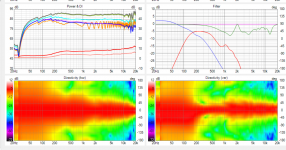
I've also made a quick sim attempt in the meantime, it could be tricky to get it working reliably due to the damping, etc.
This was for a 12" woofer -


This was for a 12" woofer -
Perhaps worth looking at a bit of classic textbook, before digging too far into cylinder cabinetry:

With regard to resistive ports covered by damping material, this is an area I struggled with in Akabak myself some time ago. In principle, the easiest way would be to sample the acoustic impedance across a surface covering the port from the inner side and use this as a radiation source. I couldn't find a good way to do this though - you can add a field across a plane and change it to sample impedance, then export the data, but ooooh boy it's a lot of sample points.
Worse yet, they don't seem to have useful positional data to hand, nor can they easily be mapped back to a surface or plane in Akabak.
The other way is to use the LEM part to model the acoustic resistance and mass of the material, then couple this to the radiating plane at the port exits. Just make sure the driving source is the same as that of the LF cone and HF diaphragm, otherwise Akabak/Abec doesn't model the mutual coupling.
To be a realistic model, you want the complex impedance of the material as measured in plane wave tube or similar. The absorption coefficient that is typically published only includes the absolute magnitude of the Za, so you’re missing reflection and resistance data.
The guys at Odeon put out a paper about estimating the impedance from the simplified absorption coefficient, but the method is a bit beyond me:
https://odeon.dk/pdf/BorisMondet_Internoise2017.pdf
Last edited:
That's a very different situation. There's nothing wrong in placing a circular source in a cylinder just big enough to accomodate it - try it. What you show is for a point source placed in a large baffle - very different results.Perhaps worth looking at a bit of classic textbook, before digging too far into cylinder cabinetry:
Last edited:
Interesting project here... 😀Perhaps not yeah. I'm gonna try 15" on the summer, even if the pattern control didn't mean much the leaking box reduces boxy sound and enables to use the minimal baffle and box, easy time building another for a pair after the prototyping is done 😀 big enclosures are pain to make and take lot of space. I need to test the variety in order to know which works better for what. Talk on the forum and shady personal ideas are hard to translate into idea how it would sound, only prototypes help on that.
https://www.audiosciencereview.com/forum/index.php?threads/big-2-way-cardoid.20728/
This thread even has youtube videos which shows what happens to sound as we move to sides due to the radiation pattern.
Sure, but not everyone in these threads is as up to speed on the limits of a concept as yourself.
There is also the effect of the rear of the cylinder on the output, which you can see above 1kHz on both of your quick models. That could limit the usefulness of such an enclosure if the LF driver is to be crossed with shallow slopes, such as in a passive cabinet with phase alignment as a goal.
Some of this stuff becomes more clear when you map an observation field around the enclosure in the BEM, and change the mapping to phase rather than sound pressure. You might want to set a minimum value of -180 to make the colours easier to read.
I'm sorry but I see such caveats as unsubstantiated, given all the things that come into play here.
I think if I was going to augment the LF directivity of a large waveguide speaker, I'd probably go with a supercardioid response. Slightly higher DI (5.7dB vs 4.8dB) and better rejection of reflections from the near side wall and front wall, assuming the speakers are toed-in to cross in front of the listener.
I do wonder how much (if any) audible benefit there would be, however. As previously noted, there would not be much difference above 400-500Hz with a 12 or 15 inch midwoofer.
I do wonder how much (if any) audible benefit there would be, however. As previously noted, there would not be much difference above 400-500Hz with a 12 or 15 inch midwoofer.
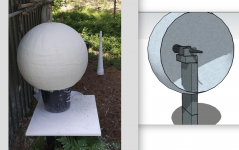
I think I simulated that before and compared to a "raw" free standing device it was actually no improvement.Now, put a ATH horn i these spheres....
The latest free standing waveguides are really good in many ways. It won't be easy to improve upon that.
- Home
- Loudspeakers
- Multi-Way
- Acoustic Horn Design – The Easy Way (Ath4)