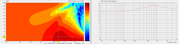
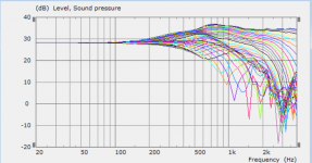
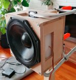
Far larger difference than I would have thought, but believable. Diffraction is greater for sharper edges - apparently a lot more.Rounded vs chamfered edges:
View attachment 1036426 View attachment 1036427
View attachment 1036428 View attachment 1036429
Is there square corner somewhere?
This is indeed true. But it is also true that if we knew what the secondary sources need to be vs. frequency, then we would have a much better idea of what the secondary ports need to do.To me, adding more sources and DSP doesn't have the appeal.

^ this is where simulators can help, hard part is to convert the results into a real box, or at least currently before accurate simulations. Easy with active system with good and predictable control on the side woofers, but passive solution is bit more work and perhaps always requires some experimenting and prototyping. Current best performing commercial solution seems to be the Dutch & Dutch 8c, which has a cardioid mid below a waveguide.
There is not too much data on how to actually make a passive cardioid box, everyone seem to keep the secrets to them selves 😀 There is some effort by me and others in the d&d 8c thread here on diyaudio, a try to reason how it works. Some simple simulations, or emulations, were quite easy to whip up together in VituixCAD and was able to build and tune a box that works nicely after few rounds of prototypes, all posted in the thread. Although, perhaps assumptions and simulations were not scientifically accurate I found out that Basotect, or more common melamine sponges, worked out nicely for passive cardioid ports in this application, which is 8" mid on a 3-way system. Melamine sponges have nice standard size, good and rather cheap availability and Basotect datasheet shows absorption coefficients and perhaps any other data one might want to know to simulate material for the ports.
I think passive cardioid are great set of compromises to use in home audio setting, even if it wasn't for the pattern control there isn't much resonance and diffraction problems since the box can be minimal, and vents out the backwave. Cheap and easy to build (eventually, if not counting zoning in a working design with multiple prototypes) and work nicely as standalone unit, like freestanding waveguide. Main downside is that it covers only few octaves before bass boost is needed, perhaps not easy to use with passive crossover. I had some measured almost flat DI (could be made rising as well) but the dispersion is still kind of wide, similar to just using big baffle. I think main benefit is being small and have directivity control to very low frequency, a disconnect of wavelenght to physical size just with waveguide does but the opposite. Waveguide makes tweeter physically big, passive cardioid can make woofer physically small, almost a cheat. Another benefit would be the ability to make pattern anything between cardioid and almost dipole by controlling delay on the back sound, point nulls towards horizontal early reflection considering toe-in. For example attenuation toward front wall can be more than with an open baffle speaker in case of ~45 degree toe-in, nice thing for on-wall system at least. There is not much attenuation towards vertical early reflections though. Did I mention easy and cheap build and considerably less all kinds of box problems? 🙂
It would be very cool if we could simulate passive cardioid systems and then build them predictably without too many prototypes. Thanks taking a stab at it!
Last edited:
Honestly though, I don't see much need for cardioid in home situations unless they can work to lower the DI of the main source at its passband HFs. Otherwise any directivity factors get washed away below Schroeder.
I'd agree, and add that there is much focus on what results are pleasing to the eye, and less regard for what matters or what is audible.
I worked with Fluid to start my own investigation into edge treatment. This is a little more typical than mabat's example above. Nominal 17cm woofer and either 32mm chamfer or roundover.
Attachments


Last edited:
The box dimensions seem to be amplifying the issue.Is there square corner somewhere?
This is like a worst case scenario where the driver is a small flat disc with virtually no directivity, the box dimensions are similar in width and depth and both sides being chamfered isn't helping.

Like in the images from augerpro above in many situations the differences between a chamfer and roundover can be much less pronounced
Cardioid woofer would be a great way of achieving higher and controlled DI down to lower frequencies (not necessarily Schroeder) without a need for a huge woofer and waveguide. That's the appeal I see. When I say woofer I mean this: smallish(WG + cardioid midwoofer) + subwoofers. Take a look at a typical 15" woofer + WG combo (which is already quite big in my book) - at 1 kHz the DI is already falling. Is that the best we can do?
- Of course the bigger the better, it's just that it's not so big advantage then.
- Of course the bigger the better, it's just that it's not so big advantage then.
Last edited:
https://www.diyaudio.com/community/...-design-the-easy-way-ath4.338806/post-6973631Is there square corner somewhere?
That's what I have been chasing all along.Cardioid woofer would be a great way of achieving higher and controlled DI down to lower frequencies (not necessarily Schroeder) without a need for a huge woofer and waveguide. That's the appeal I see. When I say woofer I mean this: smallish(WG + cardioid midwoofer) + subwoofers. Take a look at a typical 15" woofer + WG combo (which is already quite big in my book) - at 1 kHz the DI is already falling. Is that the best we can do?
- Of course the bigger the better, it's just that it's not so big advantage then.
Having a high DI lower down will shape the power response (and the PIR) but maintain a closer to ideal on-axis/LW.
Room integration EQ will still be mandatory but IMO it's a better starting point.
Anything befow 120Hz could be omni.
However, I see DSP and multiple sources more flexible as one may "easily" tune the DI to adapt somewhat the speaker to the room.
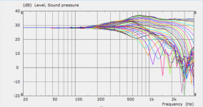
Yeah the d&d 8c for example has nice smooth DI. My box is not as smooth by the looks of the measurement results found online but very nice performance for not much bigger box than the driver itself (8"). There is about ~15db attenuation towards front wall at 200Hz from ~21x21x15cm object, not too bad 🙂 "Flattish DI" around 6db from ~300Hz > 1kHz. Manipulating box internal and external dimensions I suppose one can adjust this more, perhaps deeper enclosure of the d&d 8c is optimized to extend the flat DI part lower than mine is able to. 8c seems to be very well optimized design and worth looking at. I wanted to keep mine as small as possible to make it couple with the wall as high as possible, it is for on-wall speaker system.
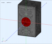
Attached is photo of the box on a measurement rig and normalized polar plot in 10 degree increments. Gated livingroom measurements.
Attached is photo of the box on a measurement rig and normalized polar plot in 10 degree increments. Gated livingroom measurements.
Attachments

Do you think that an axisymmetric structure would work too? That would probably be my first attempt.
- I consider this to be a great result, BTW. It seems it can't be that difficult 🙂
- I consider this to be a great result, BTW. It seems it can't be that difficult 🙂
Last edited:
Do you mean round box, as barrel or bullet? Why not, go for it, square box is easy to made so went with it. I'm having it identical on all four sides. Dimensions are rather small in comparison to wavelength except you might want to enlarge the outside while keeping the inside small in order to optimize both the (driver) front and back sound as you need to manage both to get them cancel out. Remember, on a dipole system the front and back idealy match each other and cancel very well, a nice wide bandwidth constant directivity. All we chase here is to change the pattern to remove some of the back radiation, right, perhaps have the null at angle we want to? Otherwise just use Open baffle.
You can find all kinds of information how a resistive passive cardioid box works but not much practical info how to actually build one. Like Linkwitz description that draws analog to electrical circuits, but I've imagined the system a lot simpler and never figured out what the resistance is for, for example 😀 Not sure if this is correct but here is what I've found out, if it helps:
all you want to do is to match the backside and front side response at the aperture (like dipole), perhaps to some optimal direction of your choosing. Count in what comes around the corner from the front, a low passed (bafflestep) with some delay to it. You could sim a closed box with equivalent dimensions to see what it is to an angle. Basically you need to low pass the back signal in order to match the frequency responses of both front and back. Then you'd need the amplitudes be the same (but opposite polarity, as they are) in order to have effective cancellation, maximum attenuation. Third thing is the timing, both should arrive at the port simultaneously, or more closely if nothing was done to the back signal you get dipole and as the back side is delayed the pattern turns from dipole to super cardioid to cardioid and anything between. And of course everything is frequency dependent (due to reflections inside the box and what not).
If you sum up these few basic concepts you'd want the back side sound low passed some, delayed some to account front sound coming around the corner + what is required for pattern, but not attenuated almost at all in order to have effective cancellation. Basically you manage the acoustic path length difference and frequency response but try to not attenuate any extra. This translates to real physical box like so: you'd want to exit all the sound from the box as soon as possible so keep the (inside) box as small as possible and apertures big and free flowing (open baffle performance). You'd want some damping material in order to reduce resonances and reflections inside the box. You'd want optimize transmission through the aperture damping by angling the damping material on the port to make incident angle normal to surface reduce reflection etc, anything to minimize sound from cone to box and maximize sound through aperture. For damping material you need something with suitable absorption coefficients for frequency dependent attenuation which also makes some (group) delay. Then you'd need suitable aperture size to inside dimensions to account some acoustic low pass (in addition what happens in the driver structure already). All these need to be orchestrated to get the frequency response (and delay) match what is outside. To get fine tune the delays you'd probably need to tune the acoustic path length difference. Experiment position of the aperture, as close as possible to the baffle is good start. To increase delay of the front wave, in order to compensate too much delay on the back due to damping and what not, you can mount the driver backside of the baffle like in 8c, for example.
These are easily tested with active cardioid if you wish, in order to get idea what is required, how much delay is required to catch super cardioid response for example or if the back signal is attenuated 6db how it affects the cancellation. You could figure out some metameterial / channel structure to make all this happen inside the box without damping material but at the same time there probably is some resonances going on so you'd want some damping material in there. This in turn adds delay and attenuation, both of which you don't want too much or you cannot reach the performance you are looking for. Getting too much delay and attenuation on the back signal is rather easy, and if there is damping material and additional structure you'd probably overshoot and end up with moot cardioid response. But, if you have both attenuation and structure accurately simulated, you can perhaps use the other to tune/compensate properties of the other to get wide bandwidth problem free response. When you find a system that has little attenuation and not too much delay you'll reach the very useful super cardioidish pattern with great attenuation and constant DI.
Anyway, million things seems to affect and interact but basic reasoning and imagination seems to get quite far. I'm sure simulating all this accurately is a lot of work but perhaps doable. I'm not able to imagine this further and cannot do more elaborate simulations than emulating the simple delays, frequency response manipulation and attenuation in VituixCAD. Hopefully you come up with something nice everyone can use!😀
edit. here is the 8c thread where I have posted all the details, emulations, prototypes, dimensions and though process, there are fluid and others commenting as well with some BEM sims https://www.diyaudio.com/community/...eaker-insipired-by-d-d-8c.369939/post-6763700
Last edited:
I must add I haven't done any distortion measurements of the box and suspect that perhaps at higher SPL levels the apertures would change operation some especially when the melamine sponges aren't glued up to the enclosure, they probably resonate and leak around. Well, anyway, I think this is better performance along with free standing waveguide than closed box mid I had earlier (mid and waveguide incorporated all together with bass to single enclosure) but the latest DIY achievement always sounds the best doesn't it?🙂 Everyone should do their own research if cardioidish is something that works with their own system and application.
I think it is a good idea to have a passive cardioid, wave inside doesn't create issues since it is leaked out and handled by the front wave. Also the front wave doesn't have too much issues outside with the room as some of it was already consumed to "cure" the backwave. Winwin situation. Combine with 3D printability and it is a triple whammy for mids between Schroeder and waveguide. Only drawbacks I've been able to notice is that DSP and additional bass unit are kind of mandatory to get most of it, as well as waveguide for tweeter to match the directivity but these are good for any loudspeaker concept so not really any downsides for passive cardioid mid in my book. Quite contrary, compromises are pushed from audio to cost and complexity, and even that balances out some if the tweet and mid part of structure is 3D printed.
I think it is a good idea to have a passive cardioid, wave inside doesn't create issues since it is leaked out and handled by the front wave. Also the front wave doesn't have too much issues outside with the room as some of it was already consumed to "cure" the backwave. Winwin situation. Combine with 3D printability and it is a triple whammy for mids between Schroeder and waveguide. Only drawbacks I've been able to notice is that DSP and additional bass unit are kind of mandatory to get most of it, as well as waveguide for tweeter to match the directivity but these are good for any loudspeaker concept so not really any downsides for passive cardioid mid in my book. Quite contrary, compromises are pushed from audio to cost and complexity, and even that balances out some if the tweet and mid part of structure is 3D printed.
Last edited:
Thanks for the elaboration. Well I'm still working (VERY slowly) on one of my designs which is an all-passive three way. I didn't plan any back radiation utilization but it would be just great if I could make the midwoofer radiate in this manner. Just in idea. Otherwise I would make a whole new design built around that idea from the start, using also a free standing waveguide.


^^^ I suspect there is not much difference between any two well performing systems, or if there is the other works better on some other parameter than the other, for example on the cost. Just make a well performing speaker what ever it is, without obvious issues, and you are golden 🙂 for on-wall application cardioid enables to reduce effect off the wall proximity quite a lot, at least in theory. Haven't confirmed by measurement, sims and listening seems good. Above frequency where the speaker is not close enough the wall to be within 1/4 wavelength it has attenuation south of -15db towards the wall specular reflection point greatly reducing its consribution. Aproaching in wall system but with toe-in, and without taking down the wall! All in all, direct to reverberant sound is increased as DI is elevated down to Schroeder.
Last edited:
Thanks for the elaboration. Well I'm still working (VERY slowly) on one of my designs which is an all-passive three way. I didn't plan any back radiation utilization but it would be just great if I could make the midwoofer radiate in this manner. Just in idea. Otherwise I would make a whole new design built around that idea from the start, using also a free standing waveguide.
Exciting looking design!
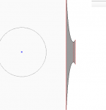
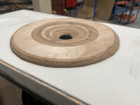
I've gone for a rear 2.8cm deep exponential aperiodic port. I use a machined open cell rigid foam (35kg/m3) to fill the grey highlighted volume. This port is directly behind the 12P80ND.
Attachments

In my design there's a small closed volume for a 12" midrange and a 4th order band-passed 15" woofer in the rest of the cabinet. That was my idea for a passive full range speaker at that time (it dates back maybe to 2017).
- Part of the initial plan were big custom passive radiators for the band-pass. That was abandoned a long time ago so there's this awkward vent under the midrange driver 🙂
- Part of the initial plan were big custom passive radiators for the band-pass. That was abandoned a long time ago so there's this awkward vent under the midrange driver 🙂
Last edited:
- Home
- Loudspeakers
- Multi-Way
- Acoustic Horn Design – The Easy Way (Ath4)