That was measured in some particular horn. Your case may be very different. It's not trivial to tell what is caused by the driver itself, i.e. what will always be there (more or less). With exceptions, that is usualy break-up related and not quite in this frequency range.
BTW, such equalization is easily done in crossover design (provided it is something that can be equalized in the first place). I can't imagine how would you try to achieve that by a horn shape optimization.
BTW, such equalization is easily done in crossover design (provided it is something that can be equalized in the first place). I can't imagine how would you try to achieve that by a horn shape optimization.
Thought so, thanks!
limacon, are you new to diy? You seem to be a quick learner 😉
If you haven't already read it, this thread might be of interest.
Particularly Nate Hansen's and Augerpro's replies on page 2 are insightful.
If you haven't already read it, this thread might be of interest.
Particularly Nate Hansen's and Augerpro's replies on page 2 are insightful.
...does the "pull...out-of-the-wavefront-trick" somewhat better...
Do you, or anyone else, have reliable data on this "trick"?
I have never seen a clear analysis of the theory- so a direct comparative demonstration would be very educational.
Best wishes
David
My previous question regarding the frd data in ABEC was related to "designing out" the dip in response of the HF146 instead of using filters. Does this hold any merit?
FWIW, the response provided by FaitalPRO for the HF142 shows a similar dip, but the dip is not present in the measurements here: Test Bench: FaitalPRO HF142 Compression Driver Coupled with LTH142 60degx50deg Horn | audioXpress. The horn is supposedly the same (LTH142), so I'm not sure why the two curves differ so much.
limacon, are you new to diy? You seem to be a quick learner 😉
If you haven't already read it, this thread might be of interest.
Particularly Nate Hansen's and Augerpro's replies on page 2 are insightful.
Always held a strong audio interest along with electronic engineering. I own a company that historically has manufactured domestic stair lift upholstery. In the last few years we have moved into aerospace cabin interiors and in doing so built up quite the pocket battleship with onsite tool making, cnc machines and foam injection technologies. Which in turn lends itself to this thread.
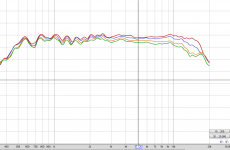
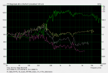
1/12th smoothing. On axis (red), and then approx every 15 deg. Will be more scientific about it tomorrow with better room treatment. I'm also making a foam covered MDF rig for the UMIK stand so I can set more precisely at 7.5 deg intervals.
Tools used
UCA202 - NwAvGuy: Behringer DAC Modifications
EV DC ONE (analogue for now but looking for AES option)
MC2 T4-250
UMIK-1
REW
Tools used
UCA202 - NwAvGuy: Behringer DAC Modifications
EV DC ONE (analogue for now but looking for AES option)
MC2 T4-250
UMIK-1
REW
Attachments
Last edited:
Don't think that was gated either. Will check REW settings in the morning and run again with the new mic rig.
What tools do you suggest to measure impedance/frequency?
What charts and at what smoothing/gating settings would you like to see?
For comparison HF146/XT1464
FAITAL HF146 (Driver 2.56", 8 Ohm, 160 Wmax)
What charts and at what smoothing/gating settings would you like to see?
For comparison HF146/XT1464
FAITAL HF146 (Driver 2.56", 8 Ohm, 160 Wmax)
Last edited:
For impedance I use LIMP from ARTA package (could be used virtually for everything): ARTA Download
Room treatment is irrelevant once measured gated. For that you need to see impulse response and limit that to the time before the first reflection arrives. Usually then there is no need to smooth it further but 1/12 (or more) should make no harm either for the purpose of crossover design. I have no experience with REW. For all frequency response measurement I stil use HOLMImpulse, which is extremely intuitive in this regard.
BTW, the results look very promising so far.
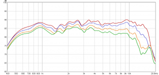
Thanks. I'll look into that. Added gating. 1/6 , 1/12 , 1/48 attached.
I've seen a few horns droop at 1K to 2K with the HF146. What part of the cd/horn/baffle geometry could this be related to? If any.
Will compare to XT1464 also.
I've seen a few horns droop at 1K to 2K with the HF146. What part of the cd/horn/baffle geometry could this be related to? If any.
Will compare to XT1464 also.
Attachments

Last edited:
This is strange, doesn't look right to me. I doubt it represents the anechoic behaviour. I would expect it to be pretty smooth at least up to 3 kHz (and flat between 1 - 3 kHz), I see no reason for the responses shown.
- If this was a correct measurement, something would be wrong anyway.
- If this was a correct measurement, something would be wrong anyway.
Last edited:
Sure, you need plenty of free space to get sufficiently long reflection-free time, at least 4 to 5 ms in this case. Not only between the source and the mic, but also around both (it makes a reflection-free ellipsoid with the source and the mic as focal points).
BTW, for anyone trying for something rectangular, I would recommend to start with this set of parameters (maybe SEExp could be lowered), which already proved to work exceptionally well, even in several diferent sizes:
It was here before: Acoustic Horn Design – The Easy Way (Ath4)
It should be easy enough to adapt the parameters to fit whatever size required - change the depth or coverage angle(s).
And again, this is the latest (still unofficial) release: http://www.at-horns.eu/release/ath4x.zip
Code:
ThroatDiameter = 25.4             ; [mm]
ThroatAngle = 27                  ; [deg]
Coverage_Horizontal = 85         ; [deg]
Coverage_Vertical = 85            ; [deg]
Depth = 95                          ; [mm]
Depth.ConicSectionPart = 0.2
Shape = raw2rect
Shape.FixedPart = 0.2
Shape.CornerRadius = 35.0        ; [mm]
SEExp = 8

Total width x height = 260 x 260 mm (10.2 x 10.2")
It was here before: Acoustic Horn Design – The Easy Way (Ath4)
It should be easy enough to adapt the parameters to fit whatever size required - change the depth or coverage angle(s).
And again, this is the latest (still unofficial) release: http://www.at-horns.eu/release/ath4x.zip
This is strange, doesn't look right to me. I doubt it represents the anechoic behaviour. I would expect it to be pretty smooth at least up to 3 kHz (and flat between 1 - 3 kHz), I see no reason for the responses shown.
- If this was a correct measurement, something would be wrong anyway.
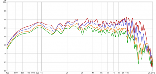
Doesn't look much different from other measurements of the 1.4 Faital drivers with Ketone Polymer dia.
Nearly all of these show some variation in the response, often with a dip >2k.
3 plots of a HF144 (16 Ohm) + 18Sound XR1496. The first is a quick and dirty (raw) response and the second and third with 6 PEQs applied.
Attachments
-
 01_faital_fh144_18_sound_XR1496_indoor_1m_4.75v_distorsions.png29 KB · Views: 408
 -
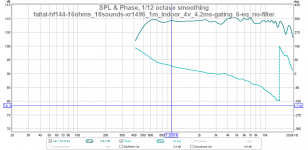 00_faital-hf144-16ohms_18sounds-xr1496_1m_indoor_4v_4.2ms-gating_6-eq_no-filter_freq-response.png95.6 KB · Views: 410
 -
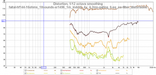 01_faital-hf144-16ohms_18sounds-xr1496_1m_indoor_4v_4.2ms-gating_6-eq_no-filter_distorsions.png134 KB · Views: 172
Last edited:
The XT1464 wil most likely yield a slightly flatter response due to the Tractrix contour and subsequently better driver-horn interface.
We need reliable anechoic polar data masured at sufficient distance. The bumps in 1 - 3 kHz range are hardly caused by the driver which is too small to cause such phenomenon. There is obviously some diffracted or reflected sound coming along. Let's wait for another attempt for measurement. Maybe a photo of the measurement setup would help here. For all horns I ever measured this was the least problematic frequency range which really should go smoothly without a glitch (it may still need an equalization but that is not the issue - that's not even possible here).
- Home
- Loudspeakers
- Multi-Way
- Acoustic Horn Design – The Easy Way (Ath4)