Sure, that's what I had in mind. It should be always better to go from smaller angle to higher angle (driver -> wg), than the other way around, so if there will be such an endeavour, the throat angle will be around 30 deg.
Well, there's one more option, and I'm not sure it would be a better solution, but the waveguide could be split into two parts: an injection moulded standard body (starting more or less conical at some bigger radius) and a 3D printed throat/mounting adapter with whatever angle needed.
You can add 10° exit angle for Celestion CDX1-1747 to your list, danibosn.
mabat, I am confident with some cross forum advertisement, the financial means for an injection mold can pretty sure be raised. At least I expected much higher costs for the tooling. A marvel of our times would be a budget friendly high performance waveguide from your software! I am also very interested in CE360.
It is a bit wider than what I would prefer aesthetically: a horn that is sized just the width of a 12" woofer and fits on a tight baffle. If at some point in time, a rectangular M2 style waveguide that fits a 12" woofer baffle will be realized, I might jump on this train, too. But the superior performance of the CE360 waveguide is a good reason to buy a set: I'd join a kickstarter!
Out of interest: What happens if the waveguide sits on the baffle, at least with it's lower half? Due to driver spacing and volume considerations, I would install the CD inside a cabinet's upper portion and the waveguide would not really stand free, maybe the upper half. Can I consider the negative effect to be small?
Well, there's one more option, and I'm not sure it would be a better solution, but the waveguide could be split into two parts: an injection moulded standard body (starting more or less conical at some bigger radius) and a 3D printed throat/mounting adapter with whatever angle needed.
Was thinking about this too, but what is needed to calculate the variety of custom throat-angle pieces? Is this possible to create a mouth curves from i.e. 10° to 30° and join them at some junction to the common upper CE360 waveguide?
That's hard to quantify without an experiment. What I can say is that once there is some mouth roll back, it's far less influenced by the edge surrounding areas than if the waveguide terminates into a baffle. So, someone would have to try. There will undoubtely be some negative effect, maybe not so big.Out of interest: What happens if the waveguide sits on the baffle, at least with it's lower half? Due to driver spacing and volume considerations, I would install the CD inside a cabinet's upper portion and the waveguide would not really stand free, maybe the upper half. Can I consider the negative effect to be small?
This is very interesting, could we just have the waveguide slightly proud of the baffle and half the roundover with good results? (such that after 90 degree of roundover the waveguide terminates in the baffle)
It should be always better to go from smaller angle to higher angle (driver -> wg), than the other way around
How did you conclude that? It seems counter intuitive to me. I would think that the smaller the angle difference the better. Thus, the best angle would be the mean of the angles of usable drivers.
could we just have the waveguide slightly proud of the baffle and half the roundover with good results? (such that after 90 degree of roundover the waveguide terminates in the baffle)
I would think that this would be fine since that's basically what I did.
Somehow I got this impression from the experiments. I now prepared again some examples where I concentrated on this. Honestly, these seem to be so little differences that it probably doesn't matter at all.How did you conclude that? It seems counter intuitive to me. I would think that the smaller the angle difference the better. Thus, the best angle would be the mean of the angles of usable drivers.
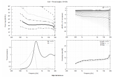
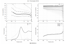
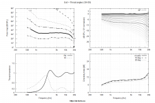
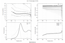
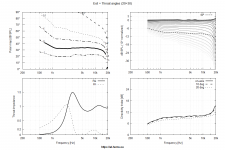
Set A: waveguide with 20° throat angle
Set B: waveguide with 30° throat angle
In each set there were three exit angles considered: 10°, 20°, 30°
(Conical exit section 15 mm deep in each case, driven with a flat source.)
Since 30+30° (exit + throat angle) seems better (with less reflection) than 20+20° to me, maybe this is where my impression came from, I don't know.
Attachments

Last edited:
I would think that this would be fine since that's basically what I did.
I meant actually proud of the baffle not just well blended with baffle having round overs.
My hunch is that "proud" would be better than "blended".
Making it stand proud you keep shadowing the edges in a smooth way. By putting it in a flat baffle you expose the nearest edges, which are in fact right at the end of the waveguide profile, where the flat surface starts.
But it's extremely ugly that way, IMO. 🙂
Making it stand proud you keep shadowing the edges in a smooth way. By putting it in a flat baffle you expose the nearest edges, which are in fact right at the end of the waveguide profile, where the flat surface starts.
But it's extremely ugly that way, IMO. 🙂
Last edited:
My hunch is that "proud" would be better than "blended".
Making it stand proud you keep shadowing the edges in a smooth way. By putting it in a flat baffle you expose the nearest edges, which are in fact right at the end of the waveguide profile, where the flat surface starts.
But it's extremely ugly that way, IMO. 🙂
If the box has radii corners then it is the nearly same as taking the waveguide back. There is a small difference in path lengths from edge to corner, but this is probably a good thing. At HFs, the wavefront is not going to see beyond the mouth edge to any appreciable degree. Free standing or in a radii baffle, I don't think there is going to be a big difference. I like using this space to enlarge the woofer box however.
I still don't like the discontinuity in wall curvature at the joining with the flat baffle, no matter how rounded is the box. The farther away from mouth this is, the better, IMO. With free standing, this happens so that it virtually doesn't affect the frontal response. For a rounded box, I'm not so convinced.
Could the waveguide have some kind of flange part way along the bell so that it could still seal a flat baffle with a smaller than the waveguide cutout and sit proud? I don't think this would effect performance as a free standing waveguide and wouldn't be visible from the front.
Here are fluids results on the effect of a woofer box on a freestanding waveguide:
https://www.diyaudio.com/forums/mul...aker-build-abec-modelling-18.html#post6510277
Here are fluids results on the effect of a woofer box on a freestanding waveguide:
https://www.diyaudio.com/forums/mul...aker-build-abec-modelling-18.html#post6510277
Yeah, I think it could work just fine.
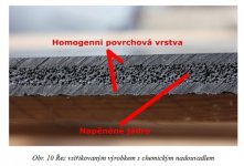
- With the injection molding, it's possible to add blowing agents that are "capable of producing a cellular structure via a foaming process in a variety of materials that undergo hardening or phase transition, such as polymers, plastics, and metals". Basically to form bubbles in the material. Would this be worth a try?
- With the injection molding, it's possible to add blowing agents that are "capable of producing a cellular structure via a foaming process in a variety of materials that undergo hardening or phase transition, such as polymers, plastics, and metals". Basically to form bubbles in the material. Would this be worth a try?
Last edited:
I once stated the assumption that a porous surface is beneficial for boundary layer separation but I was corrected by Mister Geddes, that it's not relevant for sound waves in music reproduction, as they feature dynamic behaviour. I prefer a quality plastic, not brittle, enough material but it really must not be a tank. Users can apply as much dampening material to the back until they think their subjective optimum of deadness is reached. Whether this is imagination or not. I will most probably apply layers of paint to the WG to fit the cabinets and room, they will seal of any porous surface.
Marcel, can you show what a 10° exit on a 10° mouth does in your simulation? Just out of interest.
Marcel, can you show what a 10° exit on a 10° mouth does in your simulation? Just out of interest.
Last edited:
This wouldn't exhibit on the surface, I guess, only in the internal structure. It would be lighter and by my intuition less prone to a high-Q ringing (i.e. better damped) but I'm not sure about that. Most probably the wall thickness could be increased considerably this way.
(Picture taken from https://dspace.tul.cz/bitstream/handle/15240/20598/V 119-16 Sb.pdf?sequence=1&isAllowed=y)
(Picture taken from https://dspace.tul.cz/bitstream/handle/15240/20598/V 119-16 Sb.pdf?sequence=1&isAllowed=y)
Attachments
Last edited:
I would cast a vote for a 1" CE460 with 4x4" midrange mounts. 😀
I would be in for this if the 4" was this: 4NDF34 LF Drivers - B&C Speakers
This wouldn't exhibit on the surface, I guess, only in the internal structure. It would be lighter and by my intuition less prone to a high-Q ringing (i.e. better damped) but I'm not sure about that. Most probably the wall thickness could be increased considerably this way.
(Picture taken from https://dspace.tul.cz/bitstream/handle/15240/20598/V 119-16 Sb.pdf?sequence=1&isAllowed=y)
Does this save per piece manufacturing costs?
- Home
- Loudspeakers
- Multi-Way
- Acoustic Horn Design – The Easy Way (Ath4)