Do you have a picture @jzagaja ? I'd be interested in seeing, how you fit everything together. ThanksI printed empty MEH (3 perimeters, 3 top and bottom) and filled with odorless epoxy (Epidian 652) - knock test and it's like stone.
It was meant solely for the ease of manufacturing. Otherwise it doesn't seem to be the best shape for a waveguide. The beamwidth widens on the lower end of the passband, compared to the earlier truncated version.
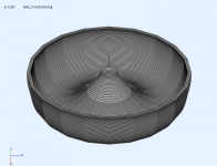
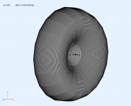
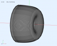
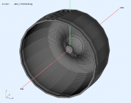
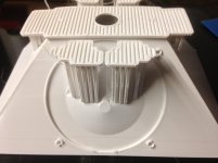
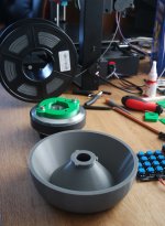
This is the "sandhorn" rolled back all the way back to the throat plane (⌀400 x 110 mm) -
This is the "sandhorn" rolled back all the way back to the throat plane (⌀400 x 110 mm) -
Attachments
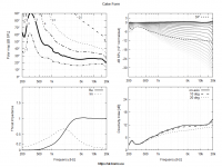
So this is it - the standard device for measuring the shape of the exit wavefront.
It was designed to be easily printable on a small 3D printer.
Now I'm going to print it myself and try to acutally measure and calculate something. If it goes well, this should become available to anybody interested enough to contribute.

It was designed to be easily printable on a small 3D printer.
Now I'm going to print it myself and try to acutally measure and calculate something. If it goes well, this should become available to anybody interested enough to contribute.
Attachments
Do you have a picture @jzagaja ? I'd be interested in seeing, how you fit everything together. Thanks
Only made during epoxy filling. I don't recomend gluing if you print open chamber, lot of post processing. For gluing I use methacrylate glue (TPU) or epoxy resin with collodial silica in this example (PLA).
PLA glue well with cyanoacrylate glue.
Attachments
Nice thanks @jzagaja are you 3d printing the mid enclosure? Can you please show the backside?
I'm in the process of doing 3d printed MEH throat and wood mouth, if I can get my CNC figured out ...
I'm in the process of doing 3d printed MEH throat and wood mouth, if I can get my CNC figured out ...
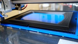
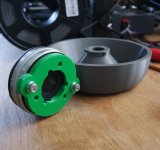
I've sent to end user for evaluation. Pictured - PETg can't be printed open chamber because bent, PLA can. Build plate from TPU stick to both. I print cold bed because my printer is 1x1 meter and Anet A8plus is too small. I could CNC this but model is in STL and no time for decomposition.
Attachments
Now I'm going to print it myself and try to acutally measure and calculate something. If it goes well, this should become available to anybody interested enough to contribute.
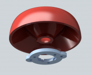
Looking great! I like the twist and lock feature of the mounting plate. Looking forward to this. Thanks for all the awesome ideas, much appreciated. [emoji106]
To summarize - print mouth down, at once, gyroid low infill, top layer 0, fill with self levelling concrete. If you need divide model use Luban.
I've sent to end user for evaluation. Pictured - PETg can't be printed open chamber because bent, PLA can. Build plate from TPU stick to both. I print cold bed because my printer is 1x1 meter and Anet A8plus is too small. I could CNC this but model is in STL and no time for decomposition.
Perfect thanks for the pictures. I'm a 3d newbie and have not graduated from PLA yet but having a lot of fun With 3d/CNC challenges LoL... it's great seeing Your work pieces and see what's possible... Thank you
CNC machining is not simpler either. MDF is weak material for thin passages and you need double side machinig with carefull model division - Vectric Aspire is easy soft for this. Best would be combining cnc and printing like Thermwood. I'm now working on pellet extrusion but I need fibers to stabilize warping. Then material price is 1-5$ per kg.
Last edited:
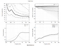
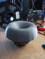
I'm pretty satisfied with the result, the mounting lock works like a charm. The waveguide print took about 10 hours with 0.4 nozzle and 0.24 mm layers. I switched to PLA for the waveguide without adjusting the retraction setting (the mounting adaptor is PETG), maybe it could be improved, no big deal.Now I'm going to print it myself ...
Attachments
Last edited:

Maybe "locked" is not the right term. "Fixed in place", perhaps. It's pushed against the foam so it's not free to move. It works really well for the purpose of this experiment.How mount adaptor is locked?
There could be some flexible mechanical "lock" as well, it's just not necessary.
Last edited:
So this is it - the standard device for measuring the shape of the exit wavefront.
It was designed to be easily printable on a small 3D printer.
Now I'm going to print it myself and try to acutally measure and calculate something. If it goes well, this should become available to anybody interested enough to contribute.
Looking forward to the files for this to become available please Marcel.
May I suggest inclusion of an adaptor plate for screw-on CD's as this would be useful for comparing performance of this interface vs bolt-on.
Thank you!
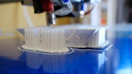
How the hell are you printing all that without supports?!Calculation with complex numbers is no problem.
- I'm finishing the "reference waveguide" design. As it is, it should be easy to print in one go, without any supports
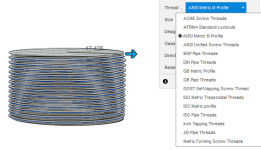
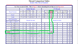
Do you know the type of the thread? I only know it is 1 3/8".
From the attached PDF document looks like its a US SAE Fine, form = B , angle = 60?
Attachments
- Home
- Loudspeakers
- Multi-Way
- Acoustic Horn Design – The Easy Way (Ath4)