If you mean the conventional compression ratio (i.e. the ratio of projected diaphragm area to phase-plug entry area), I don't see how it's related to the shape of the exit wavefront. Nor do I see how it could change with frequency. So you probably mean something different.
Or is this supposed to be somehow related to the modes inside the compression chamber? That does affect the exit wavefront but I don't see why you couldn't take all this as a black box and describe the exit wavefront independently on its own (as we do by the modal decomposition at the throat entrance).
Or is this supposed to be somehow related to the modes inside the compression chamber? That does affect the exit wavefront but I don't see why you couldn't take all this as a black box and describe the exit wavefront independently on its own (as we do by the modal decomposition at the throat entrance).
Last edited:
That does affect the exit wavefront but I don't see why you couldn't take all this as a black box and describe the exit wavefront independently on its own.
To me the driver has always been a black box. We know what we desire and expect from them, but we don't know to what extent they meet with our expectations. This, to me, should be the main goal - to create a database of driver details that are not offered by the manufacturers. Using a standard optimized waveguide would allow us to do that. As DIY, the driver is always going to be a "given," hence we should know exactly how they perform.
I just came across the same thing - it happens e.g. when the throat opening angle is wide and the source wavefront flat. To me this seems like a HOM in the WG, pretty similar in its manifestation to a higher duct mode at the source. I only still don't know how to isolate that.If I remember I think i've seen the - 0.25 lookalike results while trying out the various ath parameters few months ago (with a flat source). Need to look them up, if it could be a potential countermeasure? Not sure if I stored any of the poor looking results but if it was something real you might have seen it as well.
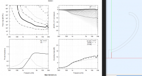
Attachments
To me this seems like a HOM in the WG, pretty similar in its manifestation to a higher duct mode at the source. I only still don't know how to isolate that.
Either I misunderstand this comment or I thought that we had gone through this (calculation of the throat modes.) If it's a waveguide HOM, which it certainly can be if the throat wavefront is not flat (and even if it is to a certain extent,) or the throat angle is not right, then it will appear in each and every driver in exactly the same way. Thus with a database of the reconstructed throat (versus frequency I should add,) then we will know what is what.
Very interesting stuff. Do I understand the current situation correctly: it is possible to design and sim "a perfect" waveguide with the ATH but since measurements of manufactured "perfect" waveguide is not perfect we have a doubt whether the measurement is "ruined" by the waveguide or the driver? And we could possibly confirm this by testing several drivers with kind of a reference design waveguide?
If this is the right situation now, then the next quest would be to design the reference waveguide to test the drivers against?
What would be the minimum size of a waveguide that would reveal the HOMs of the driver? Might be small enough to fit into a pocket? 🙂 Should be easily modified to any driver exit angle so anyone could 3d print one in few hours? This could potentially enable the community to build some kind of database for good drivers, that would measure in a waveguide as well as the sims?
Seems quite a task, maybe some university thesis project could work it out with handfull of drivers? 🙂
Last edited:
I just came across the same thing - it happens e.g. when the throat opening angle is wide and the source wavefront flat. To me this seems like a HOM in the WG, pretty similar in its manifestation to a higher duct mode at the source. I only still don't know how to isolate that.
Cool! there is interesting thing about all this, I never saw the opposite polarity phenomenon appear with random ATH flat wavefront simulation results which kind of suggests that the waveguide tends to put the HOM this polarity with flat source (off-axis peaks, on-axis dip) . But the opposite polarity corresponds to the sims done with the duct modes (off-axis dips, on-axis peak). Also in the past few real measurement examples show off-axis dips and on-axis peak, which hints the measurements have likely a bad source wavefront which confirms good waveguide? 🙂
Very unscientific here but it really feeds the curiosity so thought to write it here 😀 And still we'd need to find the good drivers.
Last edited:
Agreed. My comment didn't relate to this - when I said I didn't know how to isolate the waveguide HOMs, I meant how to show or expose them in a similar way that we can do for the throat modes - to clearly see what they are. But maybe it's even not a good question, and all the modes (throat and WG) are coupled so that it makes no sense to try to separate them, I don't know.If it's a waveguide HOM, which it certainly can be if the throat wavefront is not flat (and even if it is to a certain extent,) or the throat angle is not right, then it will appear in each and every driver in exactly the same way. Thus with a database of the reconstructed throat (versus frequency I should add,) then we will know what is what.
- When we drive a waveguide by the 0,1 duct mode (e.g.), how do we know what waveguide HOMs are propagating and shown in the result? This seems to be coupled somehow but in a completely obsured way, at least to me.
Sure, that's the plan (see #7184). Then the next step is to simulate the polars for all the throat modes that are of interest and make a program that can calculate the weights (as a function of frequency) based on a real measurement of any device on this referene waveguide.... the next quest would be to design the reference waveguide to test the drivers against?
Regarding the throat opening angle, as I understand it, for the sake of the above procedure, it should stay the same for any driver tested, i.e. without adjusting the reference WG.
Last edited:
Anyway, for a 1" throat all of this appears to happen pretty high in frequency (all the higher modes) so there's really not much to worry about. Make a smooth, diffraction free waveguide and you have it.
It will get more interesting for bigger drivers I guess.
It will get more interesting for bigger drivers I guess.
Last edited:
ah of course you already had the situation under control 😀 trying to follow along.
Yeah, sounds reasonable objective to try decompose the modes of a driver so that one could sim a waveguide more accurately. But wouldn't it be a lot simpler try and find few drivers that have reasonably flat output and just buy those, if they exist? At least knowing how much difference there is between the good and worse would be fine start? So anyone could have peace of mind they are using good enough driver.
Yeah, sounds reasonable objective to try decompose the modes of a driver so that one could sim a waveguide more accurately. But wouldn't it be a lot simpler try and find few drivers that have reasonably flat output and just buy those, if they exist? At least knowing how much difference there is between the good and worse would be fine start? So anyone could have peace of mind they are using good enough driver.
I don't know where it will lead to (if at all) but just having at least a small survey is probably what could be expected for the start. The goal could indeed be simply to sort out the better drivers in this regard, as Earl said. But of course, this is not the only (or even the most important) criterion for choosing a driver, so it may end up as fairly academic effort anyway.
If you mean the conventional compression ratio (i.e. the ratio of projected diaphragm area to phase-plug entry area), I don't see how it's related to the shape of the exit wavefront. Nor do I see how it could change with frequency. So you probably mean something different.
Or is this supposed to be somehow related to the modes inside the compression chamber? That does affect the exit wavefront but I don't see why you couldn't take all this as a black box and describe the exit wavefront independently on its own (as we do by the modal decomposition at the throat entrance).
Since different frequencies will have different volume displacement, to the compression ratio cannot be constant over a wide band. This is reality. Compression ratio at different frequencies will effect the way it expands at the horn section, specifically the velocity vector. So even if the shape of the wave front could be the same at the throat for all frequencies, the way the wave will expand will be different over a wide frquency range. The OS format tries to optimize expantion at a specific frequency, but at frequencies below that design point, the throat actually acts like a diffraction corner. This is why the foam is used to reduce HOMs.
Sorry, I have no clue what you are trying to say. This has nothing to do with different volume displacements, as all these effects (higher order modes, etc.) are independent of level.
Compression ratio is constant for a given driver, i.e. it's a single number given by its construction. You would have to provide some other definition to make it something else.
Compression ratio is constant for a given driver, i.e. it's a single number given by its construction. You would have to provide some other definition to make it something else.
Sorry, I have no clue what you are trying to say. This has nothing to do with different volume displacements, as all these effects (higher order modes, etc.) are independent of level.
Compression ratio is constant for a given driver, i.e. it's a single number given by its construction. You would have to provide some other definition to make it something else.
It’s okay, I don’t think in terms of equations, but rather in terms of physical phenomena. To many people, it may be difficult to understand.
The single number is valid if the volume passing through the device is contant. However, this is not true in real life operation, so the number is misleading.
Regarding the throat opening angle, as I understand it, for the sake of the above procedure, it should stay the same for any driver tested, i.e. without adjusting the reference WG.
For simplicity, I would agree. But, if ever more detailed analysis of the driver is desired, the more of a complication this becomes. The mismatch diffraction at the junction would always be attributed to the driver since obviously we are assuming the waveguide to be perfect.
PS. I mean "perfect" in the modeling sense since it is mathematical.
But of course, this is not the only (or even the most important) criterion for choosing a driver, so it may end up as fairly academic effort anyway.
I suspect, as stated before, by you, that for a 1" driver it is not going to be significant, hence my preference for using as small a driver as one can use for the specs. But for 2" drivers, it may be the difference between useful and not, especially as regards its high end.
Last edited:
After all, it's no problem to generate several reference waveguides along with their simulated results for each throat mode, for more throat angles. Even if for one degree increment, this wouldn't take long to prepare.
This can be a distributed effort, so no one would need all of them at once. I can imagine people contributing with just one or two measured drivers. I intend to design the waveguides small enough to be printable even on the most basic hobby 3D printer (7" - 8" max).
Last edited:
- Home
- Loudspeakers
- Multi-Way
- Acoustic Horn Design – The Easy Way (Ath4)