You really don't have to do it this way in 2021 😀I ping the source section with a true one-sample Dirac pulse and then look for reflections in the impulse
Thinking a bit more about the "excess phase correction" via a FIR DSP for the whole loudspeaker (the direct sound, that is), I think that the phase response should be set to minimum phase corresponding to the actual amplitude response, not simply zero, otherwise some very unnatural artifacts may occur. Is this how it's being done?
Last edited:
If it does you do more than the phase linearization. By definition, if applied to an input signal to speakers, it can't change the radiation pattern. So it's difficult to judge on audibility of linear vs non-linear phase response in such case if some other effects take place.
I combination with yet one more driver it can. Ans as we seldom listen to just one driver, this I think is a fair comment...?
"I ping the source section with a true one-sample Dirac pulse"... well, there could be a problem with the blindfolded belief in the FFT transformation between frequency and time plane - why, because it suggest a totally linear system in order to be fully true. A speaker isn't. And music is more than sinus (but not a lot 😉 I'm not a Fourier denier - on the contrary actually - but the steady state is a to easy stimuli...) so I wonder if it wouldn't make more/also sense to measure an actual real short pulse and transform that into a frequency response instead - and EQ it flat from this perspective instead. Do any of our favourite freeware do that? Or any program...?
//
Last edited:
If applied to the input signal, i.e. before crossover, or the same in all XO branches, it can't. That's what you have to do if you want to evaluate the audibility.I combination with yet one more driver it can.
You ask me? No, I blindfoldedly believe I will get the same result but with better S/N with the current generally used methods 🙂...Do any of our favourite freeware do that? Or any program...?
Last edited:
You really don't have to do it this way in 2021 😀
Lol.... i think i do !!! For understanding purposes anyway.
fwiw, I've now had 8 full days of in-class training on using dual channel FFT. More and more, i realize knowing what i want to measure, knowing what i am actually measuring, and understanding the time/frequency tradeoff, is the name of the game...for me.
(And i could no doubt use another 8 days training !)
It has been shown that using a pure impulse has a low SNR because all the energy is located at one point in time. Better is to spread the energy in time and then derive the impulse response from that, i.e. MLS, log sweeps, etc.
Regarding GD, I never made a claim about what could and could not be "fixed". I know all that very well and am not interested in that side of the discussion. I was curious about what the MDEGD (My Definition of Excess GD) was for system as they are actually listened to in practice. Since this thread is about simulations, little completed system results are every shown, it was perhaps not the right place to enter this discussion.
My curiosity stems from the fact that sound systems tend to sound worse at higher SPLs while at the same time we have to discount nonlinearity as the source of this problem. Neither I, nor Toole nor any other professionals that I know of believes that nonlinearity is a major effect. So what is it? Since we know that the perception of GD increases with SPL, then this could be a source for the problem. That's my interest, not if it can be corrected or not, that is beside the point.
From the scientific definition of GD it has to include the propagation delay. Removing this delay from the GD leaves a function without a recognized definition and everyone seems to have a different one - hence MDEGD. Just because someone else gives a different definition for "excess GD" does not make it a given standard definition. Only the scientific community can make that assessment and that has not been done as all the evidence points to.
Then it makes no sense to comment on group delay of non-equalized compression driver in a waveguide. Group delay of the system as a whole will be completely different, with by far the biggest contributor being the crossover.... Since we know that the perception of GD increases with SPL, then this could be a source for the problem. That's my interest, not if it can be corrected or not, that is beside the point.
Last edited:
If it does you do more than the phase linearization. By definition, if applied to an input signal to speakers, it can't change the radiation pattern. So it's difficult to judge on audibility of linear vs non-linear phase response in such case if some other effects take place.
Yes, there is more for off-axis improvement. Steep linear phase xovers are used, minimzing xover summation regions.
The way I've found to A/B phase linearity is:
First, make driver-by-driver minimum phase EQ's based on their magnitude variations (as we know, fixes their phase too). A required must at the driver level imho, both in-band and sufficiently out-of-band.
Then, using the exact same complementary type and order xovers, compare IIR to linear phase. Simply swap xover sets.
For example on a 4-way...with xover points at 100, 650, and 6300Hz....
I'll A/B complementary LR's, 24dB/oct, IIR vs linear phase....all else the same.
And do it for 48 dB/oct, 96 too.
Get's easier to hear a difference at higher order. 24dB/oct tougher to hear unless outdoors.
Polars almost always measure better steeper (which mandates lin phase ime.)
I've made a bazillion posts about all this, sorry if belaboring here.
I should add I've never had success with either mag or phase corrections on the input, that spans the entire frequency range when IIR xovers are already in place.
Seems the IIR summation regions are not suitable for corrections like that....cause they are excess phase regions 😉
I don't think that I ever did. But I also am not talking about some ideal EQ that fixes all the problems. That never happens, even if it were theoretically possible.
The fact remains that some waveguide designs will be easier to "fix" than others and some may require so much overhead to fix them that this is just not done. As I said, I am more interested in what works in practice not what could theoretically be done.
The fact remains that some waveguide designs will be easier to "fix" than others and some may require so much overhead to fix them that this is just not done. As I said, I am more interested in what works in practice not what could theoretically be done.
Last edited:
OK, I thought we look for a way how to detect HOMs. Maybe I misunderstood.
I'm not very interested in investigating excess phase or group delay (let's call it phase distortion) in loudspeaker systems in general, especially if it can be well compensated if desired.
I'm not very interested in investigating excess phase or group delay (let's call it phase distortion) in loudspeaker systems in general, especially if it can be well compensated if desired.
Last edited:
It has been shown that using a pure impulse has a low SNR because all the energy is located at one point in time. Better is to spread the energy in time and then derive the impulse response from that, i.e. MLS, log sweeps, etc.
Gotcha, thanks for expounding on MDEGD.
I realize a pure impulse has low SNR., and that nothing beats long sweeps.
I did get very repeatable data from the Dirac though, I guess cause so much of the energy was HF/VHF and being made by a CD.
My purpose with pinging the coax CD was to measure reflections back into the CD with as fine a time resolution as possible....using crazy short FFT's...wanting to pinpoint timing of reflections back into CD.
I don't remember why I left using sweeps to do this...but something moved me to try the pulse (which worked as far as time goes). I'll revisit sweeps or dual channel next time trying the coax source/mic gig.
No matter what technique one uses to get the impulse response, it should be the same in every detail, otherwise something is wrong. There is only one impulse response to a linear system (not so for nonlinear ones) hence any competent technique should get the same answer. If you are pushing the system into significant nonlinearity then all bets are off. That's the issue with a single impulse. If its level is low enough then no problem, but this technique will become nonlinear far earlier than spreading the energy.
since we know that the perception of GD increases with SPL
Interesting...I would guess, also that, GD increases as spl goes up, when GD source is acoustic mechanical but, not a filter, and is exaggerated in certain areas, as spl increase....You mentioned inductance modulation...sounds like something tied to the velocity of the drivers movement vs inertia
moving onMy point is that these things have been under control for a long time
----------------------------------------------------------------------------------------------
A mode is like an exaggerated or cancelling resonation isn't? In the CSD wouldn't this show as exaggerated decay or cancelled decay? I believe this HOM discussion is aimed towards horns/waveguides? So direct energy measurement of the bare driver is normal and the direct energy measurement with horn/waveguide attached, is the difference via CSD?
Last edited:
"modes" are a mathematical derivative and can be applied to a wide range of problems. Sometimes "modes" are resonances, but other times not. An HOM is not a resonance but a different way for a sound wave to propagate in a waveguide. It is dangerous to talk of just "modes" as they are all different - you have to be specific. A room mode is a resonance, a waveguide mode is not - very different things, but mathematically are linked to the same underlying techniques.
Do you know for sure if the 12" OSWG exhibit HOM?
//
Every driver exhibits HOMs, with or without horn.
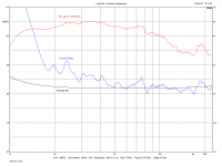
Attached are two samples of the only laboratory experiment that - to my knowledge - has ever been executed to visualize wavefront propagation and the inherent artifacts of different high freq. transducers. A raised-cosine pulse was used as the input signal.
HOMs are buried somewhere in the sea of wobble after the initial wave front (pulse).
Conclusion: if you are looking for relatively clean high freq. reproduction use an AMT, ribbon or soft-dome tweeter.
Attachments
That's not the same thing as a HOM propagating in the waveguide that originated due to the waveguide. As you can see in the above measurement, with a common CD and IIR filter of sufficient complexity you could in principle correct the frequency response of the driver completely. You can't do this with HOMs in a waveguide (other than to attenuate them with a foam, relative to the fundamental mode).
Fortunately, HOMs in waveguides, those that would propagate outside the device, seem to be non-existent to any measurable degree so far. We are still waiting to see some.
Fortunately, HOMs in waveguides, those that would propagate outside the device, seem to be non-existent to any measurable degree so far. We are still waiting to see some.
Last edited:
I use the word resonance incorrectly? If a driver is making sound I call that resonation...apparently it is incorrect...I thought the driver moving was a re-sounding or resonation of the source electrical signal....I wish I knew the technical term for it
The electrical signal oscillates first....and then the driver (re-oscillation of the electrical)....I see the same relationship with the driver oscillating first....followed by the pressure waves oscillating....hmmmmm
How is the transfer of oscillation from one source to the other not resonance and what to call it???
When something continues to resonate longer than the source I thought it was excess decay and I though modes usually end up with excess or decreased decay as opposed to the source.
How do you have sound...without resonation...."Resonance describes the phenomenon of increased amplitude that occurs when the frequency of a periodically applied force (or a Fourier component of it) is equal or close to a natural frequency of the system on which it acts."
the amplitude of diaphragm is 0...the signal via motor is the applied force....and is close or equal to the natural (13a: closely resembling an original : true to nature) electrical frequency
I usually start digging at definitions when I am confused...
I"ll show how I read "An HOM is not a resonance but a different way for a sound wave to propagate"
"An HOM is not a resonance but a different way for a resonance to mode"
Thus I'm lost....wait or did that last sentence actually make sense lol
Last edited:
Fortunately, HOMs in waveguides, those that would propagate outside the device, seem to be non-existent to any measurable degree so far. We are still waiting to see some.
Here we agree.
- Home
- Loudspeakers
- Multi-Way
- Acoustic Horn Design – The Easy Way (Ath4)