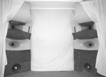
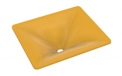
I made this to hold down through the cross, below 1k. IIRC I got about -4to5dB at the ceiling.Yes, one with a reasonably flat DI through the intended band.
A significant challenge is the throat.It's not true - rectangular waveguides don't have to have problems on diagonal - I've just shown a counter-example above.
Attachments
Your argument seems to suggest that if the device has different beamwidths in different planes (H/V/D) it can't be CD. This makes no sense to me. And if the argument is that the DI is low (the same) at LF, no waveguide would ever be CD (which it really isn't but that's beside the point).It can't be. All directions will have about the same DI at LF - they have to. So if the DI in one direction is higher than the others at HF then the total DI has to be rising.
- What I see is a rock stable beamwidth in the diagonal plane and can't see how this could be a bad thing.
(This is an IB simulation so below about 1.5 kHz it gets wider because of that. In real it will be different/narrower considerably lower, we know that.)
Attachments
Last edited:
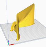
I have a 1.4" bms 4594he if the throat match? I could print it maybe in quarter sections.
Thanks. It occured to me that I still have B&C DE7 (0.75") so I can try to print it myself first. If I fail (which is likely to happen) I'll pass it to you.298x257x96 should be printable on my printer,I can measure with DE500 or CP385/Nd.
I guess I'm pretty late to the party but I've just found out that it's possible to easily thicken the lofted surface imported into Fusion from Ath simply by selecting the "Thicken" feature - basically one click and you have a printable solid, which is a lot easier than I anticipated 🙂
Attachments

Last edited:
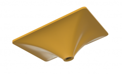
Nice. Btw, how did you come up with the dimensions of the Tritonia? Did you have a particular goal for an asymmetric pattern or did this just give the smoothest results? I'm asking because it's barely asymmetrical, but it also clearly is and I'm wondering what the reasoning behind that was.
The only reason was to make it "barely asymmetrical" - a guess, really. I'm not much in favor of asymmetrical devices, as you may have already noticed.
Sorry for the bummer but this is the "correct" result:
I think i'll brigade this thread as revenge for MABAT ruining my day with "reality" or whatever 😡
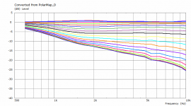
It really is remarkable how close this is to the sim once i'd corrected it. I've checked the curves in vacs, and they are pretty much all within a db or two, and the general shapes are all correct! (up to about 16khz) I can't claim my angles that are in the REW plots are very accurate (no measurement jig yet)

By working at the sim a bit more, I managed to gain back some performance. I'll consider also make it a bit bigger. Overall I'm keen to try it out in a speaker because I can already see its DESTROYING the performance of the behringer truths when i do the same normalisation visualisation

I'd like to extend this sim to include midrange taps for a synergy and see what happens

The only reason was to make it "barely asymmetrical" - a guess, really. I'm not much in favor of asymmetrical devices, as you may have already noticed.
I have noticed that 🙂 And I myself am a little torn as in isolation symmetrical devices clearly have less issues. But I also think it would be preferable to have a narrower vertical pattern in general if the drawbacks can be limited and the small forward lobe of symmetrical devices is less than ideal. And of the people who have a long history of building actual speakers Wayne Parham for example insists, that the sweet spot for a waveguide's vertical pattern is somewhere between 40 to 60 degrees. I recall Tom Danley stating that asymmetrical is fine, but the relation shouldn't exceed about 1.6:1, as the pattern flip becomes too severe to handle in the crossover beyond that point (could have gotten this wrong though). And I think even Earl has said that in theory he would prefer an elliptical asymmetrical (to what degree I don't know) waveguide, but building that just wasn't practical with what he had available. I hope I'm not misquoting him, but since he's active here, he'll correct me if needed.
I'm not saying you're wrong about preferring symmetrical devices, but there also seem to be good arguments for going asymmetrical by knowledgeable people (who in turn don't necessarily agree with each other).
Nice work measuring a real one, what are you using to measure with it is very noisy.It really is remarkable how close this is to the sim once i'd corrected it.
The argument for narrow vertical is to avoid or minimize floor and ceiling reflections which is a good idea, the problem with narrowing the coverage is that the dimension becomes smaller and pattern control is lost at a higher frequency. So you can pick narrow coverage or control to lower frequencies. Integrating two drivers with quite different directivities is not easy, 1" dome and an 8" woofer vs 8" waveguide and 8" woofer. Lots pick narrow coverage because they don't want to treat the ceiling or their customers don't. Pick your poison 🙂I'm not saying you're wrong about preferring symmetrical devices, but there also seem to be good arguments for going asymmetrical by knowledgeable people (who in turn don't necessarily agree with each other).
I think i'll brigade this thread as revenge for MABAT ruining my day with "reality" or whatever 😡
It really is remarkable how close this is to the sim once i'd corrected it. I've checked the curves in vacs, and they are pretty much all within a db or two, and the general shapes are all correct! (up to about 16khz) I can't claim my angles that are in the REW plots are very accurate (no measurement jig yet)
View attachment 922619
I have nothing against narrow vertical directivity but people seem to miss how difficult it is to achieve that without losing the pattern control: to get from 90° to 50° you would have to double (at least!) the width and the depth of the waveguide to maintain the same quality. This is no subtle thing.
Last edited:
ok i get it...you can ask questions...just don't expect an answer....or is that just certain people?
I don't have the actual numbers at hand. There will be higher order modes propagating down the tube at high enough frequencies. Different modes at different cut-off frequencies. The bigger the radius of the tube, the lower in frequency this occurs. You can look up the details in the literature.with respect to that i submit this quote from a wikipedia article:
"The duct cross section dimensions are made sufficiently small compared to the wavelength at the frequencies of interest that sound can be assumed to propagate down the duct as a plane wave with no reflections from the sides."
so does that mean that to analyze up to 14KHZ the PWT's cross section or diameter needs to be .968 inches?
- Home
- Loudspeakers
- Multi-Way
- Acoustic Horn Design – The Easy Way (Ath4)