Take a look at group delay 😉Its probably all in the impedances...
Why it shouldn't be possible?could you please elaborate how that's possible?
...
I have always been interested in porous boundaries as they would have a big effect on all but waves parallel to the surface (the zero mode). In this later case the effect would be smallish, but for HOMs it would be large.
Hi, sounds interesting since this kind porous material could be used in a MEH midrange tap as well: let the mid driver play through while simultaneously reduce diffraction effect for the tweeter that plays across the tap? I tried to search more information about this but couldn't identify one, I just don't have any knowledge on this. Could you or someone else suggest what to look for if I wanted to learn more about this difference between zero and higher modes and porous surfaces?
ps. sorry for polluting the thread with the MEH stuff but this seems very interesting 🙂
Watch it when you approach loading. For example it can be used to indicate when to cross a LeCleach horn before it gets high. Look at group delay in a good waveguide and it is gentle, you can (often) move past it.
I'd be more interested whether is such a horn a minimum phase device at those frequencies. Don't you know?
I would suspect it is. Than the loading would be just irrelevant.
- Maybe it's the right time to get the impulse responses from the simulations. Then we could extract the excess group delay. Has this been done?
I would suspect it is. Than the loading would be just irrelevant.
- Maybe it's the right time to get the impulse responses from the simulations. Then we could extract the excess group delay. Has this been done?
Last edited:
- Maybe it's the right time to get the impulse responses from the simulations. Then we could extract the excess group delay. Has this been done?
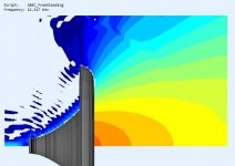
If you choose Fourier response from the processing menu in VACS you get this from an SPL contour plot, copying a single selected value to another window should give a single impulse rather than them being grouped like here
Attachments

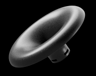

It looks beautiful! Did you consider making the back side of the mouth a half round instead of the flat end it has now? It would make for a continuously flowing shape all the way to the end cap. No sharp edges anywhere. Just a thought...
Yeah, that's the first thing that comes to mind and I totally understand what you mean. The funny thing is that this is really the best solution acoustically, despite the intuition. Don't ask me why. I tried a lot of different shapes.
I figured it had to be something like that! 🙂
Anyway, it looks beautiful as is. With a (somewhat flat) Minion shaped woofer cabinet below it should be in style 😉.
Anyway, it looks beautiful as is. With a (somewhat flat) Minion shaped woofer cabinet below it should be in style 😉.
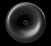
To illustrate the smoothness of the pressure field 🙂
(Grey areas are outside of the color range, i.e more than -60 dB from the throat. 3 dB step.)
(Grey areas are outside of the color range, i.e more than -60 dB from the throat. 3 dB step.)
Attachments


Maybe with this shape it's not so easy for the sound waves reflected and scattered at the back side to return back to the front, I don't know 🙂
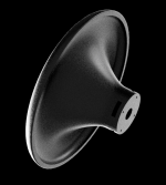
Waveguide for Faital HF1440 (⌀494 x 192 mm) going to sand printer -
Cool - did you analyse the time aspects before realisation?
//
What do you exactly mean by time aspects? I still believe it is minimum phase so there's really nothing to see (leaving HOMs aside).
All your simulations seem to be describing just one moment in time. I mean that you might want to look how a pulse injected into the throat looks at the mouth, in different directions, during a certain duration in time - say 10ms. Like a waterfall.
//
//
As I said, IF the device is minumum phase then there's nothing more to see, i.e. when equalized flat in amplitude, the phase (and the group delay) would be flat as well. Maybe it is not MP and that's probably what should be checked first.
Last edited:
- Home
- Loudspeakers
- Multi-Way
- Acoustic Horn Design – The Easy Way (Ath4)