Ernie is correct I guess.
But even from this (hypothetical) model, it is clear that the impedance rises slowly from about 1000Hz (in analogy with the Honda 6 engine) and there's no output below.
It also demonstrates that a compression driver must be coupled to a horn to become a single, highly efficient electro-acoustic system.
BTW, Honda engineers put a lot of effort into optimizing the (intake and) exhaust systems, in order to optimize efficiency of the engines.
Last edited:
I can only say from experience that in pro audio you have to obsess over these things, but for home they are mostly just very loose guidelines. Everything is SPL sensitive.
Truer words have never been spoken.... 🙂
I'll make the next one differently (this is 1" and I still have 1.4" in the making) - I'll cut the threads on the microphone holder tubes and screw them in directly. It will mean the holes in the PWT will be 10 mm instead of 8 mm but it's probably not worth the extra effort.
During the weekend I'd like to make some initial calibration.
During the weekend I'd like to make some initial calibration.
Last edited:
I'll start a new thread as soon as I have it all prepared and actually running. This will be a great adventure 🙂
Before I drill the holes into the second tube, I have a question that came to my mind when reading what was discussed before: Wouldn't it be better to reduce the distances between the mics, i.e. move them all closer to the source? This could be done by placing them opposite to each other, or 90 deg apart around the tube. And maybe also increase the number of the mics. Couldn't this improve the analysis?
Last edited:
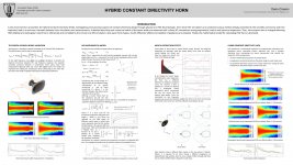
Far more interesting than B&C's ME464 imo, is this horn concept.
Although it's not better than what's possible with ATH4.
Although it's not better than what's possible with ATH4.
Attachments
Last edited:
Is he the same guy behind this horn?
Ciare PR614 - Ciare PR614 is a 1.4 inch cast aluminum horn. Ciare PR614 has a 60 x 40 dispersion. Ciare PR614 is a new generation v-shaped horn
Seems like the same few people design for all the Italian brands.
Ciare PR614 - Ciare PR614 is a 1.4 inch cast aluminum horn. Ciare PR614 has a 60 x 40 dispersion. Ciare PR614 is a new generation v-shaped horn
Seems like the same few people design for all the Italian brands.
Indeed, it is Dario Cinanni.
Just as handsome as yours truly, but in addition also blessed with beta talent.
AudioExpress article:
Just as handsome as yours truly, but in addition also blessed with beta talent.
AudioExpress article:
Attachments
Last edited:
Before I drill the holes into the second tube .... Couldn't this improve the analysis?
Posted previously I think:
Attachments
I'm afraid there's nothing in that paper about optimal multi-microphone placement for source modal decomposition 😱
Finally, it's ready.
Looks very good.
I believe that you already have the math that you need (let me know if otherwise.) The main difficulty that you will have is that the matrices will be virtually singular at many frequencies. Hence, you will have to use SVD (Singular Value Decomposition.) There are many techniques and codes that do this problem, but you will have to sort through them to find one that works for you.
Before I drill the holes into the second tube, I have a question that came to my mind when reading what was discussed before: Wouldn't it be better to reduce the distances between the mics, i.e. move them all closer to the source? This could be done by placing them opposite to each other, or 90 deg apart around the tube. And maybe also increase the number of the mics. Couldn't this improve the analysis?
The closer the mics get to each other the more nearly singular the matrices will be. (They will be completely and irretrievably singular as they fall on top of one another.) Whether or not this is an issue is TBD. If you cannot invert the matrices because they are so nearly singular then further spacing is all that you can do. So I would tend to start out with wider spacing and then narrow it down if the results don;t look stable.
I still have a lot of questions regarding the math and physics of the PWT. So far I expect to have an overdetermined set of equations and proceed by the least squares / Moore-Penrose pseudoinversion, and yes, probably by means of SVD. But first, I still need to look up the basic math of the modes in the tube - not quite sure I understand it completely.
I've found a nice article about this: https://www.prosoundtraining.com/site/wp-content/uploads/2010/01/Vol36_Jan08_whatiswaving5.pdf
I will read it two or three times more and I think I'll be ready. You know, I still need to read this in layman's terms - I know some maths but very little physics.
- Ah, this is from the "Sound System Engineering" book. I have never read that. I guess I should.
I will read it two or three times more and I think I'll be ready. You know, I still need to read this in layman's terms - I know some maths but very little physics.
- Ah, this is from the "Sound System Engineering" book. I have never read that. I guess I should.
Last edited:
- Home
- Loudspeakers
- Multi-Way
- Acoustic Horn Design – The Easy Way (Ath4)

