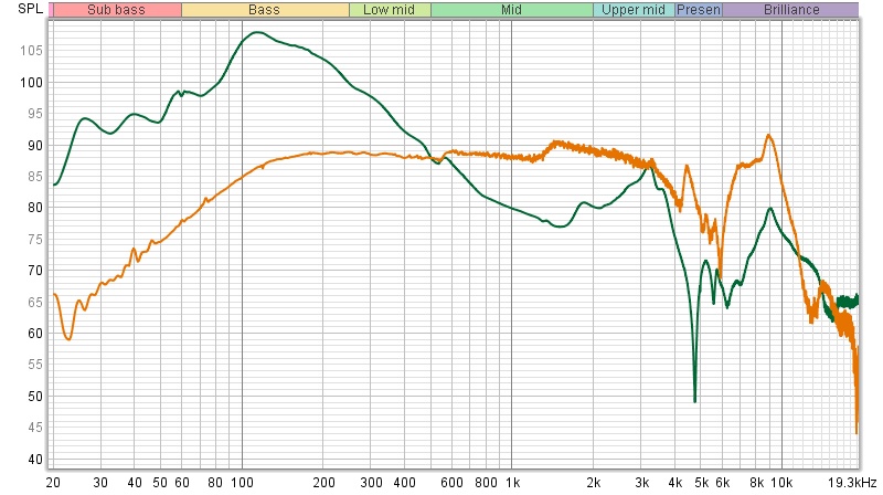
I would too, but it's still interesting from a scientific standpoint. Remember the sensor on the driver result from a few pages back with 48db per octave smoothing? It registered an obvious response. !/3 octave would have smoothed out the notches..(Orange is the acoustic response)
Last edited:
That looks like the frequency response of the piezo pivoting at 500Hz boosting the bass and reducing the treble, just like a piezo cartridge does, in the graph in post # 433 showing the treble being reduce to below the noise floor of the piezo mic?
First, either the signal generated by the sensor is accurate or not. Second, analysis of the signal by the software is what it is. The software doesn't know how it was generated. Third, what is being measured is acceleration or force/mass, not the output of a tweeter, but something related to the force generated in reaction to the force applied by the tweeter's motor. That the response is relatively flat just indicates that there is no energy storage in the panel at those frequencies. Either that of the sensor is generating a spurious signal.
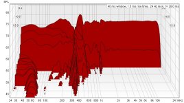
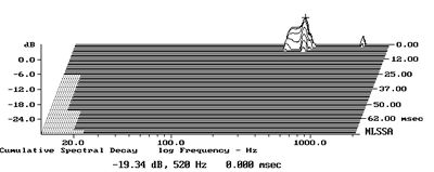
You might also redo the CSD ploy using a smaller time increment to see how the higher frequencies decay.
Here's the shorter time window, John. The reason I used a longer one earlier was to compare it directly to the dunlavy which needed the 80ms window for it's storage problems to play out. Acoustically measured, this resonance at 450hz is 40db down from the output of the driver measured at the same distance, so it looks bad but is acoustically extremely low in level
Attachments
Last edited:
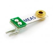
An piezo accelerometer has a known mass attached to the sensor that bends the sensor to generate a signal.
The way we are using the sensor is a little different, as we are attaching it to a surface and that surface has to bend to generate a signal in the piezo. It seems to work on guitars and even speaker box sides. I was a little worried about putting it on a cone that should be acting as a piston. If the sensor doesn't flex, would it generate a signal? It does, but maybe isn't very sensitive at higher frequencies. The Sorbothane test was interesting in that regard.
The way we are using the sensor is a little different, as we are attaching it to a surface and that surface has to bend to generate a signal in the piezo. It seems to work on guitars and even speaker box sides. I was a little worried about putting it on a cone that should be acting as a piston. If the sensor doesn't flex, would it generate a signal? It does, but maybe isn't very sensitive at higher frequencies. The Sorbothane test was interesting in that regard.
Attachments
[/IMG]
"Lightweight and very durable film tabs can be used in a wide range of applications. As a flexible Switch, a Vibration Sensor, an alarm system sensor, product damage/shock detector or as a contact mic/audio pickup. They can be mounted on any instrument that produces vibrations in addition on wind instruments as well. They produce no self resonating characteristics as in traditional ceramic piezo discs. These Film Tabs offer wide frequency response range from 0.001Hz to 1 billion Hz. They are quieter sounding than traditional ceramic piezo discs. The ground or positive may be soldered to either connector but should be wired the same in any one application. Shielding with copper tape is suggested to reduce hum in audio applications. They produce a very wide dynamic range, low acoustic impedance, high voltage output 10 times higher than piezo discs."
Features:
Wide range of applications
Thin polymer film laminate with 2 crimped contacts
Easy interface with the Basic Stamp, SX, or Javelin Microcontrollers
Did the documentation with your piezo transducer give any kind of frequency range?
It is possible (likely) that the transducer is not valid above some cutoff frequency. I don't know about other industries, but in aircraft structures, we rarely measured vibration response above 2 kHz. And we always bonded our strain gages and accelerometers with epoxy (flight and ground test) or cyanoacrylate glue (ground test only). I am suspicious that double sided tape can work at high frequencies. It will almost certainly have some damping properties, and it may partially or fully decouple the instrument above some frequency.
https://www.te.com/commerce/Documen...DS_DT_Series_without_Leads_A1.pdf11026275-00
We are mostly concerned with cabinet structural resonance below 1k anyway, so I would be comfortable in just ignoring anything above 1k...
j.
"Lightweight and very durable film tabs can be used in a wide range of applications. As a flexible Switch, a Vibration Sensor, an alarm system sensor, product damage/shock detector or as a contact mic/audio pickup. They can be mounted on any instrument that produces vibrations in addition on wind instruments as well. They produce no self resonating characteristics as in traditional ceramic piezo discs. These Film Tabs offer wide frequency response range from 0.001Hz to 1 billion Hz. They are quieter sounding than traditional ceramic piezo discs. The ground or positive may be soldered to either connector but should be wired the same in any one application. Shielding with copper tape is suggested to reduce hum in audio applications. They produce a very wide dynamic range, low acoustic impedance, high voltage output 10 times higher than piezo discs."
Features:
Wide range of applications
Thin polymer film laminate with 2 crimped contacts
Easy interface with the Basic Stamp, SX, or Javelin Microcontrollers
Last edited:
"They produce no self resonating characteristics as in traditional ceramic piezo discs. "
Meaning perhaps that if the surface doesn't bend, there is no signal?
Meaning perhaps that if the surface doesn't bend, there is no signal?
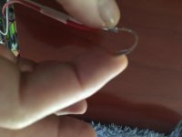
Very flexible. Is that what you mean?
Attachments
Last edited:
It is flexible and that's what makes the signal. But if it's held rigidly against a surface, how much can it flex? Obviously some, or there would be no signal.
Perhaps you could try attaching just the bottom terminals to the panel, leaving the film to "flap in the breeze" so to speak. You might need a thin spacer under the attachment point to keep the film from contacting any surface.
Toward the beginning of the thread someone mentioned using a phono cartridge. An MM cart is a velocity sensor, a ceramic cart an amplitude sensor. Not to be forgotten here.
I have a few ceramic phono carts, maybe I should try them. 🙂
Maybe something like a seismograph would be more appropriate?
https://media.giphy.com/media/ee2iyV3duvnO0/200.gif
😀
https://media.giphy.com/media/ee2iyV3duvnO0/200.gif
😀
You laugh, but I once got help from a geologist at the USGS to convert seismograph recordings into sound. 😉
Not terrible, but not necessarily great either. Does Harman believe that side panel resonance control is not that big a deal? These, as everyone knows, are some of the most expensive models.
Revel Studio 2
Revel PerformaF228be
Revel Salon 2
Performa m106

Revel Studio 2
Revel PerformaF228be
Revel Salon 2
Performa m106
Last edited:
It was a little tongue in cheek but also serious. I thought along the line of a simple reaction being read by a simple device. A bit like the weight. Maybe a small speaker that had a really compliant suspension, taped to the cab wall, couldn't motion be measured at the small speaker's terminals? No sweeps just tones.
Similar to what Rod Elliot did, I'm thinking about drilling a mic sized hole in the shop speaker enclosure just to measure a rubber mallet hit around the box. I'm interested to see if that works to identify wall resonance frequency without driver influence.
This is an interesting topic and not easy to analyze as Dr. Gedlee would/has said so, hats off fellas.
Last edited:
Instead of a rubber mallet, how about an automatic centre punch to give a repeatable " hit ". Someone in the full range section suggested that.
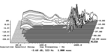
Another thing about those Revel CSD graphs. Why is Atkinson Burying much of the measurement below the graph floor? He does this more on some, and less on others. It's a practice he applies to all the panel measurements for the magazine. I believe that he thinks that under a certain threshold, the measurement is irrelevant. Does this sound plausible? Or is he doing it for a different reason?
Once again, the B&W Matrix 805. The first graph is what he could usually show in the measurements, but doesn't. Why he did this time, I have no idea..
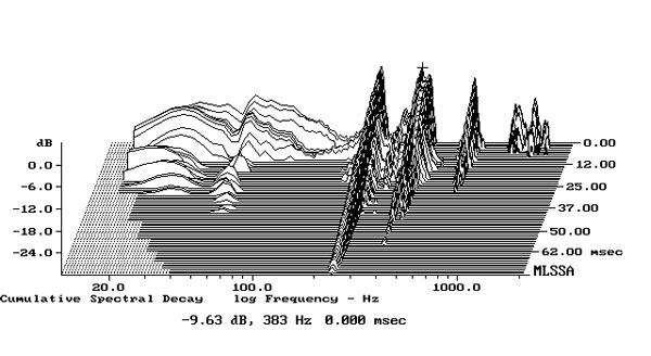
In the same review, he also posts this graph of the same speaker, with everything buried below the floor except for the peak of two resonances. This is his usual method..
Once again, the B&W Matrix 805. The first graph is what he could usually show in the measurements, but doesn't. Why he did this time, I have no idea..
In the same review, he also posts this graph of the same speaker, with everything buried below the floor except for the peak of two resonances. This is his usual method..
Last edited:
Well I don't know. We could ask him, he does drop in to diyAudio from time to time.
For me, when looking at measurements like this I'd like to know the relative level, the level as compared to what is coming out of the cone. Then I can decide what's audible and important.
It could be that Atkinson has set the floor at what he has determined as audible.
For me, when looking at measurements like this I'd like to know the relative level, the level as compared to what is coming out of the cone. Then I can decide what's audible and important.
It could be that Atkinson has set the floor at what he has determined as audible.
Like I had mentioned earlier, he sets all loudspeakers under test at exactly 5.6v input, to equal the playing field on the panel testing. He is a testing "guru" so to speak, with probably over a thousand different loudspeakers tested. I'm guessing his reasoning on the panel csd is pretty valid.(to him, anyway)
Eight years ago, he "dropped in" to protest my posting a picture of his listening(and testing) room, which is anything but optimal for the reviewing of loudspeakers🙂 Since then, he's posted several pictures and video posts involving that room, so it's no longer a mystery to his readers.
Eight years ago, he "dropped in" to protest my posting a picture of his listening(and testing) room, which is anything but optimal for the reviewing of loudspeakers🙂 Since then, he's posted several pictures and video posts involving that room, so it's no longer a mystery to his readers.
Last edited:
LOL. 😀
It's good that he has a set reference level, but my Altec horn speakers make a LOT more noise at 5.6V than my Magnepan panels do. In the speaker judging contests I've been involved in, SPL level was set with pink noise so that all speakers were are close in level as could be managed. But that was listening, not measuring.
It's good that he has a set reference level, but my Altec horn speakers make a LOT more noise at 5.6V than my Magnepan panels do. In the speaker judging contests I've been involved in, SPL level was set with pink noise so that all speakers were are close in level as could be managed. But that was listening, not measuring.
Are we sure that SPL is linear with acceleration at different frequencies?
SPL is a measure of radiated power (Watts). The power required to drive a surface in harmonic motion is proportional to acceleration divided by frequency
Power(RMS) = (1/2) * Acceleration(RMS) * Force(RMS) / angular frequency
So in other words, for 0.1 W of radiated power at 100 Hz we need a certain amount of acceleration. For 0.1 W of radiated power at 200 Hz, we need twice as much acceleration. This would be (I think) a 6 dB higher acceleration measurement at 200 Hz.
But another complication to this line of thinking is that we are rarely dealing with one single frequency, we are dealing with a broad band spectrum. White noise is equal energy at each frequency. Pink noise is white noise that is filtered at 6 dB per octave, such that there is equal energy at each octave.
So perhaps with broadband noise signals, acoustic power (SPL) is proportional to acceleration... I am not sure. It has been too many years since the university 🙁
Any thoughts?
- Home
- Loudspeakers
- Multi-Way
- Accelerometers to measure panel vibrations?