You should get one of these tape accelerometers. They're only about $15.00(I bought two for $22), and you can plug it into your 1m ohm input, the same way you're using the contact mic. You just need to solder on wires. Perfectly flat response with no acoustic contamination.OK, that makes more sense to me now. However, I'm not using an accelerometer but a contact microphone, which is level sensitive like a normal mic. Zero signal will result in about -120dBfs on a plot. I suppose that given that, the best is to use the waterfall pots as they are used with a normal mic.
I'll likely do so. Are you sure it's an accelerometer? I thought those tape types pickups where just another form of piezo pickup.
Of course it's just a piezo, in fact it could be used as a contact mic, but it tracks acceleration on one axis in an extremely linear fashion with little or no acoustic interference. I guess I should start calling it a vibration sensor though. My bad🙂
Last edited:

Hifijim
Thank you for the explanation.
They used the term "accelerometer" in the "Uses" description.
"They are the simplest form of piezo film sensors, used primarily as dynamic strain gauges, flick sensors, pyroelectric sensors, accelerometers, touch sensors, pickups, drum triggers or contact microphones for vibration or impact detection. They can be readily adhered to a surface with double-sided tape or epoxy."
And John Atkinson describes it here, and is what he uses..
"In first the February 1991 issue of Voice Coil, then the November issue (footnote 1), Editor Vance Dickason described a low-cost accelerometer made from a strip of the piezoelectric polymer PVDF (polyvinylidene fluoride) that enables impecunious engineers to get a more objective handle on cabinet problems. Costing just $35 plus shipping (footnote 2), the transducer consists of a 4" by 1" strip of PVDF attached to a small plastic block from which emerges a short pigtail of coaxial cable. The strip is securely taped to the surface to be analyzed; the output can be fed to any of the standard industry measurement system"
"As the transducer's source impedance is high and its output when used to examine cabinet resonances is in the few tens of microvolts, I constructed a 20dB-gain, op-amp-based buffer amplifier on perforated board, and used this to feed the input of the DRA Labs MLSSA system. Fig.1 shows a typical impulse response calculated by MLSSA from the output of the transducer used in this fashion with a 2kHz bandwidth drive signal. A relatively underdamped resonance with a peak amplitude of around 15mV can be seen ringing for about 80ms. (This response was actually obtained with the accelerometer taped to the top panel of the Monitor Audio Studio 15 that I review this month.) In a sense, this is but an objective version of the traditional "knuckle-rap" test, but it does enable the MLSSA system's diagnostic post-processing power to be brought to bear."
Fig.1 Typical impulse response calculated from accelerometer output (100ms time window, 2kHz bandwidth, 20dB gain).
It must be remembered that there is no easy way of calibrating the PVDF transducer—it not being possible to easily calculate the actual acoustic excitation energy applied to the cabinet wall. Nevertheless, it at least allows cabinet problems to be diagnosed on a relative basis.
Thank you for the explanation.
They used the term "accelerometer" in the "Uses" description.
"They are the simplest form of piezo film sensors, used primarily as dynamic strain gauges, flick sensors, pyroelectric sensors, accelerometers, touch sensors, pickups, drum triggers or contact microphones for vibration or impact detection. They can be readily adhered to a surface with double-sided tape or epoxy."
And John Atkinson describes it here, and is what he uses..
"In first the February 1991 issue of Voice Coil, then the November issue (footnote 1), Editor Vance Dickason described a low-cost accelerometer made from a strip of the piezoelectric polymer PVDF (polyvinylidene fluoride) that enables impecunious engineers to get a more objective handle on cabinet problems. Costing just $35 plus shipping (footnote 2), the transducer consists of a 4" by 1" strip of PVDF attached to a small plastic block from which emerges a short pigtail of coaxial cable. The strip is securely taped to the surface to be analyzed; the output can be fed to any of the standard industry measurement system"
"As the transducer's source impedance is high and its output when used to examine cabinet resonances is in the few tens of microvolts, I constructed a 20dB-gain, op-amp-based buffer amplifier on perforated board, and used this to feed the input of the DRA Labs MLSSA system. Fig.1 shows a typical impulse response calculated by MLSSA from the output of the transducer used in this fashion with a 2kHz bandwidth drive signal. A relatively underdamped resonance with a peak amplitude of around 15mV can be seen ringing for about 80ms. (This response was actually obtained with the accelerometer taped to the top panel of the Monitor Audio Studio 15 that I review this month.) In a sense, this is but an objective version of the traditional "knuckle-rap" test, but it does enable the MLSSA system's diagnostic post-processing power to be brought to bear."
An externally hosted image should be here but it was not working when we last tested it.
Fig.1 Typical impulse response calculated from accelerometer output (100ms time window, 2kHz bandwidth, 20dB gain).
It must be remembered that there is no easy way of calibrating the PVDF transducer—it not being possible to easily calculate the actual acoustic excitation energy applied to the cabinet wall. Nevertheless, it at least allows cabinet problems to be diagnosed on a relative basis.
Last edited:
I'm pretty sure an accelerometer is a sensor attached to a known mass. But the PVDF is just a contact mic that senses vibration and turns that into voltage. Just like the ceramic disc I use. With accelerometers the math has to be done to turn its signal into a normal amplitude like a mic. At least that what the project linked earlier in the thread implied.
If your pickup were seeing no acceleration, wouldn't it have a zero output? But you measure far above zero on your waterfall graph. I could be wrong about this, the piezo does have to flex to generate a signal. Can it flex enough when taped to a box?
If your pickup were seeing no acceleration, wouldn't it have a zero output? But you measure far above zero on your waterfall graph. I could be wrong about this, the piezo does have to flex to generate a signal. Can it flex enough when taped to a box?
If it is sold as an accelerometer, then it probably does measure acceleration. It just does it indirectly by measureing strain (deflection). But yes, you are right in that it is not a traditional accelerometer.
It's a piezo pickup like the piezo discs, from everything I can read. It would need to be attached to an known mass to sense acceleration. Piezo generators are one of three types of sensors used in accelerometers, I think. An accelerometer can sense unchanging acceleration, like the 1g of gravity, or 6g in a centrifuge. A vibration sensor does not do that.
But what's more important than the name is "what signal does it output with no movement?" It looks to me like zero vibration means zero volts out (or maybe DC). When it flexes from vibration it generates a signal just like any other mic. The soundcard sees it just like any other mic, as does the software. Therefore if there is a level recorded above zero, there must be vibration.
The film type do look to have advantages over the piezo disc.
https://www.sparkfun.com/datasheets/Sensors/Flex/MSI-techman.pdf
But what's more important than the name is "what signal does it output with no movement?" It looks to me like zero vibration means zero volts out (or maybe DC). When it flexes from vibration it generates a signal just like any other mic. The soundcard sees it just like any other mic, as does the software. Therefore if there is a level recorded above zero, there must be vibration.
Remlab - I went back to post 413...when you were talking about a vibration floor, I thought you were talking about a noise floor, but now I see what you are getting at. Pano has a good point here.
The piezo transducer generates an AC voltage signal in response to deflection, and it is possible that it is wired internally to perform the differentiation to go from deflection to velocity, and then again from velocity to acceleration. v = dx/dt, a=dv/dt... But that does not change the nature of the AC voltage signal.
Since you are using some kind of sound card or audio interface to capture the piezo signal, it is capturing the magnitude, frequency, and phase of the signal. zero deflection means zero acceleration, which means zero signal.
In post 404 and 413 you have interpretted the graph above 2 kHz to be the demarcation where zero acceleration equates to some nominal signal level, but I don't think that makes sense. If your sound card is capturing some amount of magnitude in the AC signal, does this not indicate there is some amount of deflection, velocity, and acceleration? I think it does.
In post 403 you show the Dunlavy response, there seems to be a "floor" (as you defined it) at about 70 dB. You are getting well defined structural resonance at 500 -600 Hz, from 85 dB all the way down to 50 dB. But this is well below the 70 dB "floor". If the floor was was truly a floor, you would be recording garbage below 70 dB, but that is not what you are getting... it is a a quality measurement down to 50 dB.
I am not sure why the response on YOUR speaker seems to flatline above 2 kHz. Perhaps there is so little structure-born energy above 2k that the piezo is only picking up acoustic output? or perhaps the double-sided tape is no longer coupled above 2k?
Last edited:
l.
In post 404 and 413 you have interpretted the graph above 2 kHz to be the demarcation where zero acceleration equates to some nominal signal level, but I don't think that makes sense. If your sound card is capturing some amount of magnitude in the AC signal, does this not indicate there is some amount of deflection, velocity, and acceleration? I think it does.
Absolutely. Whether mic, accelerometer, or any other transducer, the software is just seeing a time domain signal which can be transformed between the time and frequency domain through an FFt.
So this means what? A perfectly flat response from 1khz and up, from my panel? I'm obviously not getting something.🙂
Last edited:
Well yes, the almost ruler flat line above 2K is odd. But you don't get that with the other speakers. Jim and John confirm that what you see there is magnitude of the vibration.
I also wonder why it's so flat, and it's strange.
I also wonder why it's so flat, and it's strange.
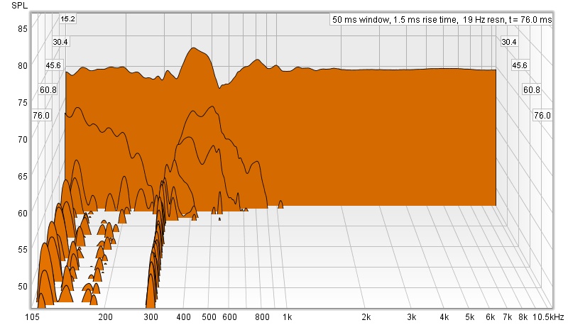
Under any circumstances, a 3/4" mdf panel will not measure better than any tweeter ever made(including decay). It's a physical impossibility, so something else has to be happening. This is why I took the "Vibration floor" argument, because I could see no other option. I'm sure the actual answer to this apparent conundrum is simple, but I don't see it🙂
Last edited:
I don't see it either. But hey, we love a mystery right? If we figure it out, we will have learned something. Maybe something important.
Would it make sense if you tilted the frequency response, lifting the bass and lowering the treble, as if the piezo mic had an uneven frequency response, similar to a ceramic ( piezo ) cartridge ?
First, either the signal generated by the sensor is accurate or not. Second, analysis of the signal by the software is what it is. The software doesn't know how it was generated. Third, what is being measured is acceleration or force/mass, not the output of a tweeter, but something related to the force generated in reaction to the force applied by the tweeter's motor. That the response is relatively flat just indicates that there is no energy storage in the panel at those frequencies. Either that of the sensor is generating a spurious signal.
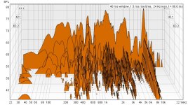
You might also redo the CSD ploy using a smaller time increment to see how the higher frequencies decay.
You might also redo the CSD ploy using a smaller time increment to see how the higher frequencies decay.
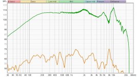
The next comparison is the graph above compared to mic measurement of the side panel(Null technique) in the exact spot of the accelerometer, Two mm from the surface. The trace above it is the actual driver measurement at the same distance. So the bottom trace can be compared directly to the CSD graph. The last is the acoustically measured side panel csd(null technique) which is even better for comparison. This is what mdf is supposed to look like🙂
Attachments
Last edited:
Did the documentation with your piezo transducer give any kind of frequency range?
It is possible (likely) that the transducer is not valid above some cutoff frequency. I don't know about other industries, but in aircraft structures, we rarely measured vibration response above 2 kHz. And we always bonded our strain gages and accelerometers with epoxy (flight and ground test) or cyanoacrylate glue (ground test only). I am suspicious that double sided tape can work at high frequencies. It will almost certainly have some damping properties, and it may partially or fully decouple the instrument above some frequency.
We are mostly concerned with cabinet structural resonance below 1k anyway, so I would be comfortable in just ignoring anything above 1k...
j.
- Home
- Loudspeakers
- Multi-Way
- Accelerometers to measure panel vibrations?