@Zen Mod
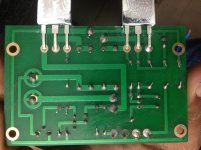
Thank you for your help, here are the pictures. What measurements you are looking for, if you could brief me on it that would be great. I use 19v 3.42 Amp adapter. The bias is set at 10v DC
triple check value of resistors and their positioning
also - be sure that signal is actually reaching pcb and that here is no some sort of short underneath
make some measurements ( few of them to check are already on schematic) and post here
I've got my mosfets on a 4U heatsink and they hardly get over ambient. Anybody with some experience on how high to take the bias and what temp. I am going to increase to 12V and see how that goes.
make difference between bias (usually some voltage somewhere) and Iq
you're asking for Iq , while mentioning setting voltage potential of output node , prior output cap
two different things , not strictly related
you're asking for Iq , while mentioning setting voltage potential of output node , prior output cap
two different things , not strictly related
Thanks Zen, patience appreciated for an old man with limited electronic background. I believe I understand what you are saying and that Iq needs to be measured possible across a resistor as previous builds and voltage increase via pot may not be related to raising iq. I increased the voltage with the pot to 12V without noticing much if any difference with temp or sound. Still sounds fantastic with horns. I enjoy SET with plenty of 2nd harmonics in spells and this amp seems to sound very SET like.
if you already have 2k2 mod , then you're done with 19V supply
if you're going to stay there , back up output node voltage where Papa sez , to preserve best symmetry and symmetrical clipping
if you want more , acquire 24Vdc brick , rebias output node 5V up and it will be both hotter and ....... hotter

if you're going to stay there , back up output node voltage where Papa sez , to preserve best symmetry and symmetrical clipping
if you want more , acquire 24Vdc brick , rebias output node 5V up and it will be both hotter and ....... hotter
if you already have 2k2 mod , then you're done with 19V supply
if you're going to stay there , back up output node voltage where Papa sez , to preserve best symmetry and symmetrical clipping
if you want more , acquire 24Vdc brick , rebias output node 5V up and it will be both hotter and ....... hotter
Understand will do, thanks.
Looking at the PCB from behind it looks like the right hand output transistor is not soldered correctly the copper trace appears to be not a plated through hole . I would re -solder and make sure the joint covers the copper trace. Just a casual observation.
It's not lead free, after solder I just cleaned the pcb with thinner it gives the neat finish 🙂
The output transistor is soldered in front and plated through hole. I will do it in back of pcb as well. The resistor values are correct and their placements. Would it be if any components are faulty?
The output transistor is soldered in front and plated through hole. I will do it in back of pcb as well. The resistor values are correct and their placements. Would it be if any components are faulty?
Ok values of R7,R8 and R14 does not measure correctly, let me change those and update you all. Thank you.
No luck, the output resistor R14 does not measure to 1K it always show as zero value when connected. Before connecting I get 0.98k, not sure why this behaviour.
Hi everyone. Is it normal to get "thump" from the speakers when the amps are turned off? My Tannoys are very efficient and they sure exaggerate this sound . Should I be concerned?
Pass DIY Addict
Joined 2000
Paid Member
I have two ACA builds, one makes a small thump at power off, the other doesn't. I've attributed this to the specific laptop power brick that each uses since they are different. Everything else is the same.
As for why kapalin's build doesn't work, check a few things. Make sure you have no cold solder joints. Make sure you didn't mix up Q3 and Q4 locations. Double check each pin on both mosfets with your DMM to make sure there is not something grounding them to the heatsink. Each should measure as an open loop. Also, check your screws/nuts where the PCB is mounted to the sink to make sure nothing is grounding or allowing a resistor tail to hit the sink.
The beauty of this circuit is its simplicity. It makes trouble shooting easy compared to the more complex designs because there are fewer things to check.
RCA Jacks: Has anyone noticed the RCA jacks are relatively shallow? I can't get any of my RCA cables all the way in. They do go in enough to work though.
Power Supplies: Has anyone built or bought 17V linear power supplies for these? Did it make an audible difference?
Power Supplies: Has anyone built or bought 17V linear power supplies for these? Did it make an audible difference?
I've attributed this to the specific laptop power brick that each uses since they are different. Everything else is the same.
So are you actually using a 24 V laptop PS on the 5 W amp? I am planning on using one of my old 24 V/4.7 A laptop power supply on my ACA 1.5 5 W amp in order to boost it's output to 6 W but I am not sure if that will cause any problem.
I saw it before but I can't find for two days now where the bridging instructions are. Can somebody please point me in the right direction?
Thanks
Thanks
Starting at steps 44 of the illustrated build guide, IIRC
Step 44 for balanced input mode, using an XLR input ( clearly the preferred option), and 46 for single ended with external resistively loaded jumper.
Note, I think Jim had mentioned the connection error in Step 48 photo - i.e. the jumper should be connected to left channel black speaker post - but it looks like the photo has not yet been revised?
- Home
- Amplifiers
- Pass Labs
- ACA illustrated build guide