MOSFET matching
Hi
i bought IRFP140 and IRFP044N and compare the transduction with my actually used IRFP240.
in my overview sheet (datasheet summary) 140 and 044N have more "Gain"
IRFP240 6,9
IRFP140 11
IRFP044N 16
actually i did the last gain setting with a 100k to get 10,3dB") and I build a filter what i had at home... CLC = 220nF+R5 - L=40µH - 820µ/50V Ruby// 33pF
and I build a filter what i had at home... CLC = 220nF+R5 - L=40µH - 820µ/50V Ruby// 33pF
still temperature is fine. @24V supply 75°C at the IRFP240..2,05A bias, DC set = 12,4V
sound is very nice.
picture will follow..
chris
Hi
i bought IRFP140 and IRFP044N and compare the transduction with my actually used IRFP240.
in my overview sheet (datasheet summary) 140 and 044N have more "Gain"
IRFP240 6,9
IRFP140 11
IRFP044N 16
actually i did the last gain setting with a 100k to get 10,3dB
and I build a filter what i had at home... CLC = 220nF+R5 - L=40µH - 820µ/50V Ruby// 33pFstill temperature is fine. @24V supply 75°C at the IRFP240..2,05A bias, DC set = 12,4V
sound is very nice.
picture will follow..
chris
Attachments
Hi TungstenAudio
hmm... with a bias current of 2,05 amps each amp i am on the limit of my small housing. the temp of the IRFP240 could be a bit more...
before i try 24V and 2,05Amps for my 4R 84dB speakers i tried 26V and 1,8Amps. it sound not much better then the normal 1,6A and 24V...its ohms law..
thx
hmm... with a bias current of 2,05 amps each amp i am on the limit of my small housing. the temp of the IRFP240 could be a bit more...
before i try 24V and 2,05Amps for my 4R 84dB speakers i tried 26V and 1,8Amps. it sound not much better then the normal 1,6A and 24V...its ohms law..
thx
measurements
4R 24Vsupply, 2Amp each side, DC point is set to 12,4V and 12,41V
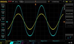
pic 1 before i got the 10,3dB i need 2400mVrms input to get 9,2WATT
2a_2400mv_in_9w_4r
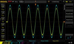
pic 2 10,3Gain_1Vrms in_4R_fg_Lchanne_2,7WATT
pic 2 10,3Gain_1Vrms in_4R_fg_Rchanne_2,7WATT
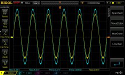
fg --> -3dB is at 120khz @4R with 1Vrms input
pic 4 1Vrms in_4R_fg_120khz_Lchannel
pic 5 1Vrms in_4R_fg_120khz_Rchannel
chris
4R 24Vsupply, 2Amp each side, DC point is set to 12,4V and 12,41V
pic 1 before i got the 10,3dB i need 2400mVrms input to get 9,2WATT
2a_2400mv_in_9w_4r
pic 2 10,3Gain_1Vrms in_4R_fg_Lchanne_2,7WATT
pic 2 10,3Gain_1Vrms in_4R_fg_Rchanne_2,7WATT
fg --> -3dB is at 120khz @4R with 1Vrms input
pic 4 1Vrms in_4R_fg_120khz_Lchannel
pic 5 1Vrms in_4R_fg_120khz_Rchannel
chrisAttachments
Last edited:
yep...for my NADA..its the best stereo ACA setup i guess. if i dont change the housing. but before i plan bigger i plan to build the other ACA with some mods and with IRF140 as you prefer ...as i read very often
now i will enjoy and compare to my brothers lateral F5..
now i will enjoy and compare to my brothers lateral F5..
Last edited:
Hi Chris,Hi
i bought IRFP140 and IRFP044N and compare the transduction with my actually used IRFP240.
in my overview sheet (datasheet summary) 140 and 044N have more "Gain"
IRFP240 6,9
IRFP140 11
IRFP044N 16
actually i did the last gain setting with a 100k to get 10,3dB
still temperature is fine. @24V supply 75°C at the IRFP240..2,05A bias, DC set = 12,4V
sound is very nice.
picture will follow..
chris
I tried a bunch of different Mosfets, including high voltage Cree's, combo's to the hilt, but in the end, I came back to using IRFQ044's. They are lower voltage, but I am only running at 24 volts now, and I preferred the more substantial lower end, they had which for my open baffle speakers was nice.
Den
Hi Den
thanks for your impressions. i am happy with the energy what the IRFP240 can do. its a bit more forward but with nice sparkling and that give me the impression to have more high end clearance. low and and sound stage could be a bit better. i know that a compare to a F5 is not fair but i like the way the ACA invest more mood for voices and higher tone instruments.
I restart to rebuild the first ACA to a premium. i want the exact same setting but just change the power mosfets.
is i read the caps are an additional part to trim the sound.
actually i am happy with my 10µ non polar /polar nichicon muse at the input. the 6800µF//10µ/10µ should be enough for low end
...will see/hear.
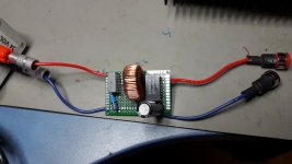
+ SMPS filter is an the way. i ordered at reichelt a 100µH coil.
i report back if i had the first impressions
chris
thanks for your impressions. i am happy with the energy what the IRFP240 can do. its a bit more forward but with nice sparkling and that give me the impression to have more high end clearance. low and and sound stage could be a bit better. i know that a compare to a F5 is not fair but i like the way the ACA invest more mood for voices and higher tone instruments.
I restart to rebuild the first ACA to a premium. i want the exact same setting but just change the power mosfets.
is i read the caps are an additional part to trim the sound.
actually i am happy with my 10µ non polar /polar nichicon muse at the input. the 6800µF//10µ/10µ should be enough for low end
...will see/hear.
+ SMPS filter is an the way. i ordered at reichelt a 100µH coil.
i report back if i had the first impressions
chris
Chris,
The 240's are a reliable friend, and when I first built my amp camp, it was of
course the standard issue part, but I became intrigued with how different parts
have their own sound character, and so I began the try this and try that! I also
was experimenting with how the amp interacted with my speakers.
I am just a shade tree fiddler, but it was a fun pursuit to try all of the different
combinations, though de-soldering became a tedious chore. Looking forward to your F5 comparison!
Den
Hi Den
lets burn give me time for compare. up to know i can say from 3 time 2 hours comparison:
the F5 (lateral not matched) is still a big sound stage and fell immediately smarter and more stoic. the subsonic area helps to get more felling that the instruments and singer have foot not knees. the sound stage is bigger at the side and a step deeper but the singer and the instruments are coming always 1meter behind the speakers.
on other hand the ACAp is more forward sound.it feels that he try much more in the upper region of the high end sounding of singers and instruments. the sound is coming more to the listener. at some titles with jazz club it feels more live.
bass is not as deep but a bit more punch.
chris
lets burn give me time for compare. up to know i can say from 3 time 2 hours comparison:
the F5 (lateral not matched) is still a big sound stage and fell immediately smarter and more stoic. the subsonic area helps to get more felling that the instruments and singer have foot not knees
. the sound stage is bigger at the side and a step deeper but the singer and the instruments are coming always 1meter behind the speakers.on other hand the ACAp is more forward sound.it feels that he try much more in the upper region of the high end sounding of singers and instruments. the sound is coming more to the listener. at some titles with jazz club it feels more live.
bass is not as deep but a bit more punch.
chris
...ACA premium with IRFP140 first channel done..
Hi
i am finished with the ACAp_2 with the nearly same setup as the other ACAp to compare just the powermosfets.
zerozone clone pcb
24V 2A bias, DC 12,4V
dale resistors. gain setting 20k to 100k ---> 11,4dB
10pF mica cap // to RF=100k
C3, input cap is 10µF bipolar muse // 1,5µF/63V wima
C2, RLN 1000µ F /16V polymer
C3 Fine gold nichicon 6800µF/35V // 100µF bipolar muse// 1,5µF/63V red WIMA
JFET is a BF245B
ZTX450
gate stopper resistor 120R
without 2k2 resistor i got just 1A - good to know for my preamp idea
with 2k2 i got 1,8A and with 0,47R parallel to both 0,68 ig got finaly 2,03Amps
220R in the drain of the J-FET (surface of the 220R is cracked)
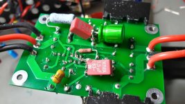
pic 1 is under the pcb...not much room
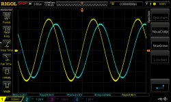
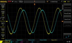
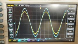
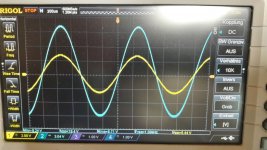
pic 2 is input 1Vrms at 4R --> gain 11,4dB
pic 3 is the first test into 4R with 1,9Vrms input and i got more then 11WATTwith 2Vrms input i got clipping at the under side...i sea too late that the DC point was not exact setup because i was interested in the max power...re measure again next days...
chris
Hi
i am finished with the ACAp_2 with the nearly same setup as the other ACAp to compare just the powermosfets.
zerozone clone pcb
24V 2A bias, DC 12,4V
dale resistors. gain setting 20k to 100k ---> 11,4dB
10pF mica cap // to RF=100k
C3, input cap is 10µF bipolar muse // 1,5µF/63V wima
C2, RLN 1000µ F /16V polymer
C3 Fine gold nichicon 6800µF/35V // 100µF bipolar muse// 1,5µF/63V red WIMA
JFET is a BF245B
ZTX450
gate stopper resistor 120R
without 2k2 resistor i got just 1A - good to know for my preamp idea
with 2k2 i got 1,8A and with 0,47R parallel to both 0,68 ig got finaly 2,03Amps
220R in the drain of the J-FET (surface of the 220R is cracked
)pic 1 is under the pcb...not much room
pic 2 is input 1Vrms at 4R --> gain 11,4dB
pic 3 is the first test into 4R with 1,9Vrms input and i got more then 11WATT
with 2Vrms input i got clipping at the under side...i sea too late that the DC point was not exact setup because i was interested in the max power...re measure again next days...chris
Attachments
Also try listening with reversed speaker polarity, you'll gain more perspective.the F5 (lateral not matched) is still a big sound stage and fell immediately smarter and more ...
Power MOSFET´s
Hi Den and all others
i check digikey...
the Cree which are tried here are all out of stock and got the double price!
C3M0160120D april...4,32...now 8,32
C3M0065090D april...7,72...now 12,34 euro
as i will try the IRFP140 instead IRFP240 with transductance 6,9 vs 11. can somebody explain me what happened if i use a POWER MOSFET with just 4 or 2,2 transductance?...Genesic..G3R160MT12D G3R350MT12D
i mentioned i have to set the gain setting much higher RF/ Rin...correct.
what is the sound if i use a Cree with less Coss , Ciss...?
chris
Chris,
The 240's are a reliable friend, and when I first built my amp camp, it was of
course the standard issue part, but I became intrigued with how different parts
have their own sound character, and so I began the try this and try that! I also
Den
Hi Den and all others
i check digikey...
the Cree which are tried here are all out of stock and got the double price!
C3M0160120D april...4,32...now 8,32
C3M0065090D april...7,72...now 12,34 euro
as i will try the IRFP140 instead IRFP240 with transductance 6,9 vs 11. can somebody explain me what happened if i use a POWER MOSFET with just 4 or 2,2 transductance?...Genesic..G3R160MT12D G3R350MT12D
i mentioned i have to set the gain setting much higher RF/ Rin...correct.
what is the sound if i use a Cree with less Coss , Ciss...?
chris
Last edited:
As a general rule, a higher transconductance will lower the output impedance, although not as much as you might like. This will reduce the effect of any ripples in the speaker's impedance plot, usually around a crossover point(s).
A lower Ciss will lower THD above 3KHz or so. When I started using IRF520s, (original 19V version) I had to dial up my tweeter control a couple of notches. Overall I'd say the amp sound mellower, but this may not be to your liking depending on you speaker and source material. Coss probably has minimal effect unless really high.
One experiment I probably don't have time for: use multiple (low Ciss) devices in parallel for Q1 and Q2 with separate (matched) Q4s for each (matched) Q1.
What device has the lowest Ciss for a reasonable transconductance and power capability ?
Thank you Loudthud.
here is my updated list. i marked all transductance with blue if the are near the original IRFP240 so i have a kind of reference.
i marked also some lower current values at 100°C or higher RDSon.
some Cree and GeneSic are low gfs...choose what you think.
very low ROHM SCT2280KEC ---> gfs 1,4
chris
here is my updated list. i marked all transductance with blue if the are near the original IRFP240 so i have a kind of reference.
i marked also some lower current values at 100°C or higher RDSon.
some Cree and GeneSic are low gfs...choose what you think.
very low ROHM SCT2280KEC ---> gfs 1,4
chris
Attachments
Last edited:
^ That is a pretty comprehensive list.
So far I have tried the IRFP140 and the FQH44N10 as alternatives to the IRFP240. My ACA-220 v2 uses IRFP140 in both positions with a linear supply that delivers over 28V to the power rail. Sounds better than a pair of original ACA in bridged parallel configuration. My F6 uses FQH44N10 throughout and sounds wonderful.
If I were building another pair of ACA boards, I would use the FQH44N10 at Q1 and an IRFP140 at Q2.
- Home
- Amplifiers
- Pass Labs
- ACA amp with premium parts