Hi Mr. Kking🙂
My selection was based on a post by JOIMONF, where he said,
Quote: Originally Posted by JOIMONF
R14, 1kohm, is critical for sound quality, and must be upgraded to maximum quality available. I heard increase sound quality using Riken resistor, then further upgrade with Vishay naked TX2352, but the definitive component here is an inductor (grid choke). I tried different values and found 2k7 to be ideal (for my 8 ohm speaker).
After some fine tuning in the power supply (Ubib by Salas), today I took another hearing on R14, as tomorrow I will get quotation for the Anode choke, wanting to be certain, I set a new arrangement, free from variables, I was lucky the magical spot was in the range I expected, the new value 2k49. For my 8 ohm speaker, this is.
Jordi
When I looked at my part stash, I had a 1.4K Dale resistor that was better quality than the 1K default R14, so I decided to try that in place as a conservative change. I did not do an intensive before and after test, but I was assuming that a better quality resistor in that place would not be adverse. I didn't have any resistors of quality any closer to the suggested value of 2K49, but my speakers are 8 ohm also.
I do not have a scope, so my comments are just from listening to my open baffle speakers, and it sounded very nice so I left it at 1.4K. Between the change of the feedback resistor to 330K plus the 27pf in parallel and the 1.4K for R14, I can say positively that my Amp Camp now exceeds the sound quality of my Tubelab Single ended tube amp, and before the tubes had the lead over the Amp Camp, though it was close. I am really enjoying the sound quality now present with the changes.
Thanks for the info, dfoulk.
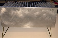
I'm in the process of using the last 4 boards of my stash of ACA 1.1 boards (the ones available at BA '17). I'm waiting on a few things to get a modest heatsink ready temporary use (in photos below), and then the testing begins (spots for a pair of 140s & 240s - for comparison in the ACA, and singles of 250 and two other lower Vgs MOSFETs - to test in my version of Juma's CapMult). Then we'll see how well each one does. Permutations and combinations, so much fun to be had! 🙂
I've modified the circuit board (cut traces) to isolate C4 and Q4 and included R16 and a wire to get the new voltage to Q4. I have also installed pots for R14 (5k) and for R12 (100k fixed + 100k pot). Most of these mods should be visible in photos below. I'll see what a bypass cap does for R12, if it seems useful later in the tuning process. I also have R15 up and easily accessible, so I can change it should I feel a need (I want to measure the current in R15 compared to that of R8 - can you guess why? - answer in PM if you think you do).
I'm using a mix of TungstenAudio's mods with yours, JOIMONFs and a few others, and a few of my own, including a funky vertical triple stack of 1000uF SilmecIIs for C1 (with space for a bypass, to be added/tested later). I also considered a horizontal stack on the sub-board, going cross-ways to the board, with two in the middle and one outboard of each board screw. The primary benefit of the horizontal layout is it allows mounting tabs to be attached to the cap board and connect to the board-mount screws (much more secure and vibration resistant).
I've also been looking at the MoFo, and I am somewhat tempted to try using inductors for the R1-R4 block. Other mods for that version would include putting a small resistor between them and C1 and relocate R15 to the far side of that resistor.
The way JOIMONF is using an inductor for the Rl position (R14 in the ACA 1.6 schematic) is interesting. I would think that one would want to get both the DC resistance correct (the Rl portion, for the tuning of (among other things) H2/H3 balance) and at the same time get the inductance correct (working in cooperation with C1 and the reactance of the specific speaker attached). That would be an interesting thing to try... eventually. While I will be working on tuning R14, the use of an inductor there will have to wait, as we're still using old JBL 2600s (best we have on hand) as our speakers. They will definitely be replaced, in the next few months...
My only worry is that I'll get bored once I finish this project... But there is the speaker project (probably a FAST setup, thus the 4 ACA boards) and a MoFo (and some ideas on that...) are waiting in the wings, so there is always that to look forward to. Then there is the Adcom GFA-555 to repair and attach to something sufficiently big... Hmmm, perhaps I can keep boredom at bay for a time. 😀
Attachments
Hi Mr. Kking🙂
My selection was based on a post by JOIMONF, where he said,
Quote: Originally Posted by JOIMONF
R14, 1kohm, is critical for sound quality, and must be upgraded to maximum quality available. I heard increase sound quality using Riken resistor, then further upgrade with Vishay naked TX2352, but the definitive component here is an inductor (grid choke). I tried different values and found 2k7 to be ideal (for my 8 ohm speaker).
After some fine tuning in the power supply (Ubib by Salas), today I took another hearing on R14, as tomorrow I will get quotation for the Anode choke, wanting to be certain, I set a new arrangement, free from variables, I was lucky the magical spot was in the range I expected, the new value 2k49. For my 8 ohm speaker, this is.
Jordi
When I looked at my part stash, I had a 1.4K Dale resistor that was better quality than the 1K default R14, so I decided to try that in place as a conservative change. I did not do an intensive before and after test, but I was assuming that a better quality resistor in that place would not be adverse. I didn't have any resistors of quality any closer to the suggested value of 2K49, but my speakers are 8 ohm also.
I do not have a scope, so my comments are just from listening to my open baffle speakers, and it sounded very nice so I left it at 1.4K. Between the change of the feedback resistor to 330K plus the 27pf in parallel and the 1.4K for R14, I can say positively that my Amp Camp now exceeds the sound quality of my Tubelab Single ended tube amp, and before the tubes had the lead over the Amp Camp, though it was close. I am really enjoying the sound quality now present with the changes.


Hi,
On my schematic, looks like R14 (1K) is parallel to the output to slowly discharge the output cap C1, why would R14 influence the sound ?
Maybe I have the wrong schematic.
BR
Eric
Hi,
On my schematic, looks like R14 (1K) is parallel to the output to slowly discharge the output cap C1, why would R14 influence the sound ?
Maybe I have the wrong schematic.
BR
Eric
Hey, Eric!
Nope, you almost certainly have the right schematic. The part numbers, although not always the values, have been the same for quite some time. If you're using TungstenAudio's "Upgraded ACA" or the ACA v1.6 schematic, you're golden.
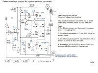
Regarding the Load Resistor:
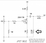
The initial design from Nelson Pass in the "jfet BOZ" thread (post #2) looked like the attached image. I am including it as I spent quite some time messing with this circuit, with potentiometers in place of nearly every resistor in order to get a better idea how each functions within the circuit. My (sometimes confused) results can be found in the posts starting at 1476 of the thread * Jfet BOZ * (presuming you use 10 posts per page).
What I'm calling the load resistor (Rl) and ACA calls R14 is in this diagram as well (look for the big arrow). It is the 2.2k resistor outside the capacitor, and it does indeed help bleed the capacitor. It also helps to act as a filter, and can help reduce the 3rd harmonic, often at the expense of increasing the 2nd harmonic. It is often used to "tune" an amp to sound more "tube like" or more "solid state" depending on if the listener likes more 2nd or more 3rd harmonic.
Personally, I prefer less of both, and use Rl to minimize THD. There are design parameters for determining a "good" value for Rl (or R14, if you prefer), but the ultimate in fine-tuning (and the ultimate test) is the ear, specifically YOUR ear.
Oh, and the output capacitor and load resistor also interact with the speaker and it's reactance (including any crossovers contained in the box). It can get complex quickly, if you try to accurately model everything in the amp and in the speaker box. Oh, and don't forget the speaker wire, capacitance and a little inductance to go with the minute resistance. Sometimes I envy the ignorant bliss of the consumer-grade people. 🙄 (not really)
Hope that helped.
Attachments
I learned something today. I haven't thought the load resistor as much of a tuning effect, simply there to help bleed the output cap when a speaker isn't connected. But it certainly is in parallel with the speaker, and would have some interaction with the speaker's complex impedance and crossover.
Something more to think about, and perhaps experiment with.
Something more to think about, and perhaps experiment with.
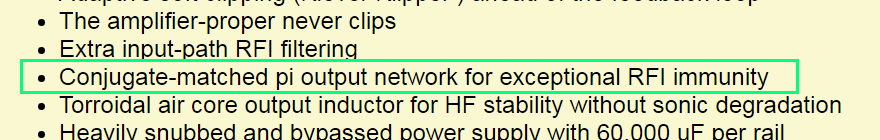
Occasionally you'll find discussions about building a conjugate matching network inside a power amp, at the driving end of the loudspeaker cable. This may be even more fun to explore, as it will depend upon the internal details of the speaker/crossover, and of the cable construction (conductance per unit length, inductance per unit length, capacitance per unit length), and, of course cable length. Lots of parameters to vary, lots of "design knobs" to adjust. Fire up the good old Latin Square Design Of Experiments, or for the extremely brave, Taguchi Methods. Woo hoo.
BTW, here is a pleasant exchange of letters between Bob Pease and myself, talking about the efficacy of Taguchi Methods. Published in Electronic Design magazine.
_
BTW, here is a pleasant exchange of letters between Bob Pease and myself, talking about the efficacy of Taguchi Methods. Published in Electronic Design magazine.
_
Attachments
I learned something today. I haven't thought the load resistor as much of a tuning effect, simply there to help bleed the output cap when a speaker isn't connected. But it certainly is in parallel with the speaker, and would have some interaction with the speaker's complex impedance and crossover.
Something more to think about, and perhaps experiment with.
+1
Thanks a lot for the detailed explanation kking.
BR
Eric
+1
Thanks a lot for the detailed explanation kking.
BR
Eric
Hey Eric and TA:
It has been several decades since transistor and FET theory classes, and never took any amplifier classes, that was analog stuff.

Interesting tidbit - I had forgotten that the Collector Resistor in BJT circuits are often called the "load resistor" as well... Sorry if that caused any confusion. To me, anything after the output capacitor is part of the load. In this case R14 also acts as a protection against having no speaker connected.
My presumption was that the Harmonic 2/3 effect was from the RC filter composed of R14 and C1, more than with the speaker, although some interaction (however small) with the speaker does exist. For reasonable values of R14, I would think that the impact on the speaker and crossover would be negligible (1k or more in parallel with 8 ohms...).
Hmmm, turns out the filter formed by C1 and R14 is a High Pass, set (using Papa's values) for a Cut-off frequency of 4.8 E-8[Hz] (per *(Sample)RC Low-pass Filter Design Tool - Result -*). So, that wasn't what I expected. That'll teach me to open my mouth before checking my memory against reality...
Ok, I'm out of ideas. I have seen it change, as I messed with the pot for Rl (in the jfet BOZ thread), and know it impacts performance, specifically H2/H3 performance. But I am now at a loss for the actual mechanism for this effect...
The capacitor blocks DC, and lets (per the math above) anything with even a thought of varying its voltage through. The R14 gives the current an alternative place to go, rather than through Q1, and shunts it to ground (as does the speaker, and more effectively, based on the relative resistances).
But how does this impact the harmonics? It isn't feedback, as it goes to ground, not back to the gate. It doesn't seem to be able to select frequencies to help usher high order harmonics out of the circuit to ground.
All I can come up with (based on the pre-amp, which has some differences) is that the load resistor, well, loads the circuit, and in doing so, alters the way it works. Not on the DC side, but on the small-signal side (if a power amp has a small-signal side)... This was seen by (at ridiculously low values of Rl) eventual attenuation of the output signal (fundamental as well as all harmonics) in the pre-amp circuit.
Just got back from some search engine work, but I couldn't get the proper incantation to reveal the answer. Nothing definite or even close to what I was looking for. Closest was a discussion of selecting load resistors (along with a capacitor) to shunt harmonics to ground for RF frequencies.

Is it time for the bat-signal? Anybody know why changing R14 would impact harmonics (specifically H2/H3 ratio)? Or is that only applicable for pre-amp level signals?
Hi
IIRC,changing the ratio of R1-R4 (0.47, 0.68ohm all 3W) will have an effect on H2,H3 levels.
That’s probably the reason they have such odd and precise values. I believe someone wrote this on this thread.
BR
Eric
IIRC,changing the ratio of R1-R4 (0.47, 0.68ohm all 3W) will have an effect on H2,H3 levels.
That’s probably the reason they have such odd and precise values. I believe someone wrote this on this thread.
BR
Eric
Last edited:
Grrrrrrrr! 😡


I'm not used to asking for help, but here I go... I had planned an afternoon of fun and experiments with mods to an ACA board, but I can't seem to get it to even start...
I have built up a pair of ACA boards before - the 1.1 boards (c)2017, from BA 2017 - they're downstairs in the family room. This shouldn't be difficult. Yet here I am, with a board that refuses to power up. By that, I mean the MOSFETs are not taking any power. The power supply is registering less than 10mA being consumed.
Here are the measurements so far:
Q2: Vgs = 0.0, VDS = 13v
Q3: all legs show 0v (Vcd, Vbc, Vbe are all 0v)
R7: 13v
P1: 6v
R9: 3v (mA thru Q4)
The voltages across R7 and Rp add up to the source voltage (starting with 19v)
The troubling thing is Vgs for Q2 - that implies a dead short bc on Q3. But the transistor tester gives the same info for the pulled unit as for the unused unit (hFE=171 & Uf=655mV), so (at least in theory) they are both good.
Even with Q3 out, the R7/P1 voltages remain, and imply 1.3mA going thru the capacitor - is that appropriate, or is the cap bad? I tried measuring resistance with Q3 out (between C & E) and got 2.7 ohms. Unfortunately, that is probably related to the capacitor, as it is across those two pins. Any thoughts?
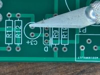
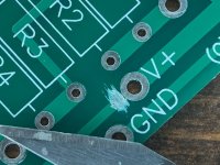
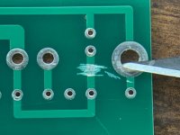
Now for the tough part... I've modified the board. I cut both traces between R13 and C4 (front and back) and the trace that brings power to the drain of Q4. These are the red boxes in the unpopulated board photo. I added a Resistor (R16, 604 ohms to start) from power (at R7) to the +leg of C4, and a jumper wire around to the drain of Q4. These are the yellow lines in the unpopulated board photo. Everything should now be hooked back up the way it was, with R16 to help keep excess voltage from Q4 (as the power supply will be going up once I get it working). The rest of the parts are unchanged, except for R11 & R12, which have nothing to do with the main current path for the MOSFETs.
There is obviously something going wrong with the setup for the constant current source. However, my degree is in digital, not analog, and I don't recall enough classes from <mumble> years ago to be of any real help.
I can get more voltage readings, if that will help. I eyeballed the resistors, and none seem to be off. I even did some in-circuit resistance measurements, and they seem to match what is expected. There are attached images, perhaps they will help as well.
-Note that the MOSFETs are bolted to a heat sink and the wires (with red, white and blue wires/heatshrink) are GDS, like the MOSFETs (as seen from this direction).
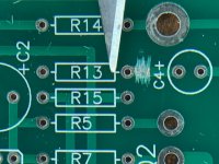
-Note that R13 & LED are not populated, and that R14 & 12 are wired to off-board potentiometers.
-Note R15 is waaaaaaaay up in the air, as I wanted to be able to get leads on it easily for voltage measurements.
-Note all three of the images (when expanded) are 'upside down' compared to the copyright lettering at the 'bottom' of the board.
Thoughts, ideas, hints, derisive laughter?
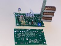
PS - I added an image of the lab setup, showing the heatsink with lots of MOSFET parts to swap out. The cluster of 3 on the left side are for the CapMult, and I confirmed the voltage loss for it matches the Vgs-on for the part. The two smaller parts have a 2V drop for Vgs, but I haven't had a chance to test it out under load to see if that is enough to be effective or not...
I'm not used to asking for help, but here I go... I had planned an afternoon of fun and experiments with mods to an ACA board, but I can't seem to get it to even start...
I have built up a pair of ACA boards before - the 1.1 boards (c)2017, from BA 2017 - they're downstairs in the family room. This shouldn't be difficult. Yet here I am, with a board that refuses to power up. By that, I mean the MOSFETs are not taking any power. The power supply is registering less than 10mA being consumed.
Here are the measurements so far:
Q2: Vgs = 0.0, VDS = 13v
Q3: all legs show 0v (Vcd, Vbc, Vbe are all 0v)
R7: 13v
P1: 6v
R9: 3v (mA thru Q4)
The voltages across R7 and Rp add up to the source voltage (starting with 19v)
The troubling thing is Vgs for Q2 - that implies a dead short bc on Q3. But the transistor tester gives the same info for the pulled unit as for the unused unit (hFE=171 & Uf=655mV), so (at least in theory) they are both good.
Even with Q3 out, the R7/P1 voltages remain, and imply 1.3mA going thru the capacitor - is that appropriate, or is the cap bad? I tried measuring resistance with Q3 out (between C & E) and got 2.7 ohms. Unfortunately, that is probably related to the capacitor, as it is across those two pins. Any thoughts?
Now for the tough part... I've modified the board. I cut both traces between R13 and C4 (front and back) and the trace that brings power to the drain of Q4. These are the red boxes in the unpopulated board photo. I added a Resistor (R16, 604 ohms to start) from power (at R7) to the +leg of C4, and a jumper wire around to the drain of Q4. These are the yellow lines in the unpopulated board photo. Everything should now be hooked back up the way it was, with R16 to help keep excess voltage from Q4 (as the power supply will be going up once I get it working). The rest of the parts are unchanged, except for R11 & R12, which have nothing to do with the main current path for the MOSFETs.
There is obviously something going wrong with the setup for the constant current source. However, my degree is in digital, not analog, and I don't recall enough classes from <mumble> years ago to be of any real help.
I can get more voltage readings, if that will help. I eyeballed the resistors, and none seem to be off. I even did some in-circuit resistance measurements, and they seem to match what is expected. There are attached images, perhaps they will help as well.
-Note that the MOSFETs are bolted to a heat sink and the wires (with red, white and blue wires/heatshrink) are GDS, like the MOSFETs (as seen from this direction).
-Note that R13 & LED are not populated, and that R14 & 12 are wired to off-board potentiometers.
-Note R15 is waaaaaaaay up in the air, as I wanted to be able to get leads on it easily for voltage measurements.
-Note all three of the images (when expanded) are 'upside down' compared to the copyright lettering at the 'bottom' of the board.
Thoughts, ideas, hints, derisive laughter?
PS - I added an image of the lab setup, showing the heatsink with lots of MOSFET parts to swap out. The cluster of 3 on the left side are for the CapMult, and I confirmed the voltage loss for it matches the Vgs-on for the part. The two smaller parts have a 2V drop for Vgs, but I haven't had a chance to test it out under load to see if that is enough to be effective or not...
Last edited:
It is difficult to tell what is going on based on the photos.
Q3 is part of the current source. Without it to control the Vgs of Q2, it won't function properly. The leakage current through C2 may be within range for the organic polymer cap being used at that location. Check the datasheet to confirm.
The ad hoc connection for R16 looks pretty dodgey. The long jumper wire looks like it could be problematic as well. This version (v1.1) of the ACA board is not as easy to modify as the later version, which is now available in the diyAudio store.
Last edited:
Here is a set of expected voltages for the ACA with a +24V supply, and standard values for R1 – R4. This should give you good targets to shoot for. The Drain of Q4 will of course be lower based on your choice for R16.
Thanks for the reply, TA. Unfortunately, none of those values can be achieved until I get the CCS running (Q3/Q2). The main difference between your drawing of mods and my layout is I didn't get 121 ohms for the MOSFET stoppers.
Was there a specific reason to bump those values up by 20%?
Yeah, the photo was taken after I removed Q3, and yes, without it, the CCS is a non-starter. Oddly enough, the voltages I observed were the same with and without Q3 in the circuit.
If Q3 is open circuit (blown), then the voltage split between R7/P1 sets the Vgate of Q2 at about 6 volts, which is where Vsource would be for Q2, absent any voltage across the fractional ohm power resistor block. This leaves the Vgs well below operating range, and Q2 shut off tight. The argument in favor of that is the circuit behaved the same way with the device present as well as absent.
If Q3 is shorted, Vgate for Q2 should see the same value, but now current flows around the capacitor (not sure if that matters). However, Vsource for Q2 now differs by the voltage drop across R8, which is (in series with the power resistor block and Q1) the alternate path for P1. Unfortunately, R9 was showing low 3volt range, so not far enough up to start Q1, so that makes R8/power resistors a dead-end path, no current in R8, no voltage across R8, and Vgs on Q2 is roughly zero. So shorted would show the same response, if my analysis is correct.
Any thoughts on what I've laid out so far?
Yeah, I tend to overthink things, but I don't like to just burn parts up without thinking about it first. If I screwed up something that is blowing up Q3, strapping in the next victim will only leave me 2 parts down, with no additional hints on a solution. Yet the cheap-o transistor tester still claims the part is functional, giving the same hFE and Uf numbers as the unused part... Sooooo frustrating.
As for the photos, yeah, they don't compress well. Not sure if that's the phone, the e-mail program or the web site display, but they're ugly.
R16 is sufficiently functional for the moment, if somewhat ugly. It will be done better once the values of the parts it is attached to are finalized. It will probably be routed from V+ at Q2 drain directly to C4+. Much cleaner, but not the way I wanted to go at the moment. As for the long wire, did you see the trace it replaces? It goes from V+ to the C1 end of the board, doubles back around the pins for Q1, and then finally gets over to Q4. Not very pretty either. Such is life. I try to lay things out so the audio travels the shortest distance possible, and cluster parts by function around that, also trying to minimize trace lengths. I doubt it matters much for these boards, but it's an OCD thing...
For example, the layout of the v1.1 board. If R13 was pushed closer to R14, the existing trace from R3/4 to C2- and Q3e could go through the new gap between R15 & R13 on the front, and the trace on the bottom from R13 V+ side could have shot through that same gap and made it to the drain of Q4 in about half the distance. But it should work perfectly fine either way.
As for what's in the DIY store, what matters to me is what I have in the parts box already. 8) Did I mention I'm cheap?
As for the circuit mods, I can't see how I could have butchered the layout on that (not that you accused me of that, just thinking out loud and laying out all the possibilities I can think of for this failure). There was nothing else on the trace from V+ to Q4d, so cutting that should impact nothing except the audio front end (ie no impact on the CCS). I can try shorting R16 and see what happens (after I put Q3 back in), that should restore the circuit topology to the original layout (just to remove a variable).
I just realized something... There is a remote possibility that at 19v, R16 is limiting the current flow through Q4 to the point that Q1 won't turn on (Vr9 has already been confirmed as being too low, as it measured a little over 3v), and the stoppage is actually in Q1, not the CCS. Both Q1 & Q2 have to be on for any appreciable current to flow. If Q1 is off, we have 19v trying to push through the 5k resistor P1, resulting in what, just under 4mA, right?
Since my voltage across R9 is low, that is certainly part of my problem. R10 along with P1 provide a positive bias to Vgs for Q4, and if the DC current flowing through Q4 is insufficient, it cannot raise Vgate enough over ground to turn Q1 on, and everything grinds to a halt...
Did I mention I hate analog? Hahaha! Oh well, I guess I know what I'm doing for the next couple evenings...
Thanks again for the help, and some of the circuit ideas. This will eventually be fun!
Last edited:
I sometimes like to "voice" my amplifiers a little differently. The gate stopper resistors form an RC network with the input gate capacitance of the power Mosfets. The ACAs in my system tend to be run fairly hard into my medium efficiency speakers, and sounded better to my ears with a slightly higher resistance for the gate stoppers. (My choices of feedback resistor R12 and capacitor C101 were made for similar reasons.)
Having R8 and R15 in parallel with the power resistors R1 – R4 makes little difference in the current when Q3 is not installed. The leakage current through C2 is likewise fairly negligible, given that P1 can be adjusted as necessary to compensate. Hopefully your N-channel JFet for Q4 still works. Those parts are somewhat sensitive to static discharge.
The value you've chosen for R16 won't be an issue with a +19V supply. It will simply reduce the Vds of Q4, which still has some headroom. Remember that the P1 adjustment will result in about 4 mA to 4.5 mA of current through Q4. That same current will flow through R16.
At this point it is probably time to verify that the resistors have the correct values, and are making proper connections in the circuit. Do this with the power off. The current source is a simple circuit, meaning that a simple error is probably responsible for the problem.
After saying I was not going to mess with changing my Amp Camp anymore, I have a meal of my words!
Ordered a pair of new 1.6 boards from the DIY store, and plan to build a new set with good quality everything. Will add the 2.0 ohm in parallel with R3 as before. Gate stoppers R5 and R6 will be 150 ohms. Feedback R12 will be 332K, and R14 will be 2K. The FET protector, R16 will be 499 ohm. Using 1K cut the voltage too much, even running the rails at 29 volts. C3 will be a 22uf Muse bi-polar with a .01uf by-pass. I had a 470uf for C4, but since I have finally gotten my linear power supply dead quiet, 330uf will be plenty large. I will keep Q1 a IRFP044, and a IRFP140 in Q2 position. For C1 I have been using a Gold Nichicon 4700uf, 63 volt, with a .01uf polystyrene by-pass, like on C3. The 63 volt rating is larger, but it fits snug. Previously I had a 47uf Elna bi-polar for C3, but the 22uf will be generous, and fit better on the board.
When it gets together, I will let you know how it sounds in comparison to the first generation model.
R14 experiment
Yesterday I hooked up a 5K pot with my current 1.4K value R14, so I could
try different values while I was playing music. I hooked it up to the left channel
and the right side default for comparison. From observations of other posts,
it has been determined that the quality and value of R14 does indeed influence the final character of the Amp Camp sound.
When comparing the sound between the 1.4K for R14, and dialing in 2K for R14,
there was a noticeable change in the sound coming out of my open baffle home brews. My speakers, which present an average resistance of 6.1 ohms to the amp, as I go up to 2K for R14, the sound is pleasingly more full sounding.
Among cd's I was testing, a mono copy of Beatles '65, with the 2K, almost sounded stereo in comparison to the 1.4K side. If AM radio had sounded that good, FM would have had a tougher sell! Classical guitars, voices, all seemed to be more 3-D. Sounded like the 2K value let the sound out of the box so to speak in comparison to the 1.4K side. I really like the the 2K value much better than the 1.4K. I can't remember what it sounded like with the default 1K value, except that I liked it better when I changed it to 1.4K. All of these perceived changes I am sure depend on the speakers and speaker cables, etc. of the individual system you have, but I will go with the 2K for my setup. Beyond 2K, the sound is not balanced, with the mids becoming muddy in comparison and over bearing. The change from 1.4K to 2K would not be that perceivable unless you can compare the two on the fly. Before I thought that 1.4K was great. Sure is a testament to the adaptability and abilities of this gem called the Amp Camp Amp! I am glad that I have one, and I am looking forward to my rebuild on fresh boards with all top quality parts. My amp is running on 29 volts. Also I have Q1 a IRFP044, and a IRFP140 in Q2 position. Will post when I have the new one all together and singing🙂
Hi Dfoulk, I remember also same muddy sound, or congested, compressed sound you describe when R14 back to 1k. My reseach was slight different, instead of a pot. I use an asortement of different values permalloy inductors I have bought cheap in Ebay long ago. Copper resistance 550R, 1k67, 2k7, and higher. My first try was parallel 1k67 and 2k7, (=1031R) that is a nice close up to 1k wanted for comparison. Glad I do, inmediate sound improuvment over Vishay naked TX2575. Next try was compare this 1k031 to an 2k7 copper resistance inductor. I liked that last and wants further more, arranged for comparison 550R + 1670R ( in series)= 2220 ohmmic copper resistence. The sound was roughly the same as 2k7. Not having any value in between using inductors, I finally found my preferred 2k39 by help of a pot. Not remembering right now if paralleling to 2k7 or in series to 2k22. It worth the hassle finetuning the best spot with precision, as soon at 2k40 or 2k38 starts to degrade. (In my case of course) I think R14 sets the amplifier damping factor that may be adjusted for any particular speaker.
Another very picky value I found is R6. An important resistor, only one in signal pass. I use here 104,5R (23V.power supply ACA driving 8 Ohm spkr)
Another very picky value I found is R6. An important resistor, only one in signal pass. I use here 104,5R (23V.power supply ACA driving 8 Ohm spkr)
Last edited:
I sometimes like to "voice" my amplifiers a little differently. The gate stopper resistors form an RC network with the input gate capacitance of the power Mosfets. The ACAs in my system tend to be run fairly hard into my medium efficiency speakers, and sounded better to my ears with a slightly higher resistance for the gate stoppers. (My choices of feedback resistor R12 and capacitor C101 were made for similar reasons.)
Having R8 and R15 in parallel with the power resistors R1 – R4 makes little difference in the current when Q3 is not installed. The leakage current through C2 is likewise fairly negligible, given that P1 can be adjusted as necessary to compensate. Hopefully your N-channel JFet for Q4 still works. Those parts are somewhat sensitive to static discharge.
The value you've chosen for R16 won't be an issue with a +19V supply. It will simply reduce the Vds of Q4, which still has some headroom. Remember that the P1 adjustment will result in about 4 mA to 4.5 mA of current through Q4. That same current will flow through R16.
At this point it is probably time to verify that the resistors have the correct values, and are making proper connections in the circuit. Do this with the power off. The current source is a simple circuit, meaning that a simple error is probably responsible for the problem.
Thanks for the info on the stopper resistors. I may try something once I get the final speakers designed and built.
Again, the picture was taken with Q3 out, it is normally in. While it was out, it allowed some measurements to be taken with better part-to-part isolation. Sorry for any confusion about Q3.
I pulled each active component, and they all test in my cheap transistor tester to be the same as before they went in, and match the other 3 sets of parts (within a reasonable margin). That seems to indicate the actives are not the problem.
I also checked each resistor visually, and tested them in-circuit (thus the comment about R8 (in conjunction with the power resistors) & R15 being in parallel). Everything seems to be as expected.
That leaves me with two possibilities
- I botched the cutting of traces, which seems unlikely, as I shorted R16 and everything seemed to measure (resistance wise) as expected (point-to-point, based on what is in parallel or series).
- one of the capacitors is having trouble, which might be remotely possible, as I didn't check them before putting them in.
The next step is to pull the caps and check them. If that's not the issue, I will re-attach the damaged traces and see if it starts working again. This has been extraordinarily frustrating, but that's what I get for not measuring, marking and verifying each part.
Basics: skip them, and you ask for trouble.
Update:
C2 was "bad" - replaced it with a Panasonic electrolytic of 1000uF 16v and it powered right up. The bag of Panasonics all measured in the high 920uF to low 940uF on a 1000uF nominal, so less than 10% down. Well within spec.
The "old" one measured closer to 1500uF, although I didn't think to measure it before putting it in. Not sure if it was always bad, or if I somehow "killed" it, but the others in the bag (from Mouser) all measured a few tens of uF over the 1000uF designation.
I'm going to check some things out with the Panasonic in there, then try the RNL part again, and see if (for whatever reason) they don't like me, or if it was just that first one.
Lesson (re-)learned - never skip the basics!
R14 experiment
For what it is worth, on my setup of open baffle speakers, with my Amp Camp, running at 29 volts, with 15 volts at idle, with a Stan Warren unity FET buffer as my pre-amp, R14 in my re-build, will be 2K paralleled with a .33uf capacitor.
This is based on by-passing R14, and replacing it with a 5K potentiometer, set at 2K. This brought the greatest clarity compared to the default right channel that has a 1.4K for R14, which sounded better to me than 1K for R14.. The value of .33uf for the parallel capacitor is the approximate amount of capacitance added to the 2K resistance by the potentiometer.
I have not found that increasing beyond 2K for R14 adds anything positive, and I have discovered that as the amount of resistance increases via the pot, the amount of capacitance of the pot appears to decrease.
My open baffle speakers present a 6.1 default load to the amp. I would assume that each individual set of speakers would probably be different, but I share this in case someone would be curious to fiddle with this variable. I thought that I would explore this because I wanted to finalize my parts before I solder up my new boards. This is a subtle, but noticeable improvement on my speakers. The Amp Camp is a great amp, enjoy the music🙂
Dfoulk you're right, maybe my limited english, I don't think you must further increase over 2k as same in my system.
I simply share my method for fine tune with precision the best spot.
What's happened, once I heard the 1k choque that replaces R14 resistor, I try hear other resistor values using a pot, I may use also a 5k pot most likely, but not success this way, because I could'nt forget the 1k. choke sound just heard minutes back. So no matter moving the dial pot, I dislike everything, and took the other route I explained before (comparing differents chokes).
- Home
- Amplifiers
- Pass Labs
- ACA amp with premium parts