Yes, remove R12 transforms amplifier to current source. Great for fullrange speakers only.
I have found another modification for all users, including those with multiway speakers with crossovers:
The input filter R11/C3 can be deleted and placed an input capacitor 3,3uF instead. I am using temporarily an external PIO with teflon bypass. A mess I know but not having a Miflex or Jupiter copper in wax. Take care shielding the wires if noise. Much compact solution is 2,2uf Slimic II + 1uF policarbonate for input. (Of course also one 3,3uF Elna Silmic do the trick).
A warning, I am not electronic engineer, for me is good remove input resistor, I'm using transistor preamp Salas DCB3.
Last edited:
It is always interesting to hear how others have experimented and thank you for sharing
your discoveries! I currently have an Elna BP for the input cap which sounds very good.
I am using a modified Superphon CD Maxx line stage as my preamp, a solid state FET design, and it works well with the amp camp too.
your discoveries! I currently have an Elna BP for the input cap which sounds very good.
I am using a modified Superphon CD Maxx line stage as my preamp, a solid state FET design, and it works well with the amp camp too.
R14, 1kohm, is critical for sound quality, and must be upgraded to maximum quality available. I heard increase sound quality using Riken resistor, then further upgrade with Vishay naked TX2352, but the definitive component here is an inductor (grid choke). I tried different values and found 2k7 to be ideal (for my 8 ohm speaker).
The Vishay naked found later great place in R9, much better than Riken there.
The Vishay naked found later great place in R9, much better than Riken there.
Nice Dfoulk, you yell me please if try, although not guarranted, Mr. Pass may place her arrangment for protection in different scenarios, which I don't understand.
Now the kits have 24v Meanwell PSUs. A nice improvement, But costs about 7x what the generic 19v ones did!
Should mention that the mods on this thread are at your own risk! Just because someone says it’s an amazing improvement it’s their opinion and when you do something maybe there’s a bit of bias there, no pun intended. Not singling out JOIMONF at all, just speaking generally.
Should mention that the mods on this thread are at your own risk! Just because someone says it’s an amazing improvement it’s their opinion and when you do something maybe there’s a bit of bias there, no pun intended. Not singling out JOIMONF at all, just speaking generally.
Last edited:
dfoulk, you're using fullrange also?
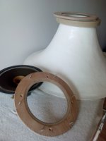
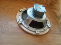
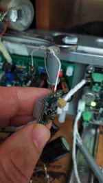
This is my speaker driver, Rullit Classic 8", it has bakelite spider inside, delivers lifelike in low level, so called microdinamic. Then is a resin front horn, great for macrodynamic, one speaker (mono) is enough to fill the room, but for modifications better close the ear to the speaker mouth, and can hear every change. Very sensitive to any capacitance in excess.
This is my speaker driver, Rullit Classic 8", it has bakelite spider inside, delivers lifelike in low level, so called microdinamic. Then is a resin front horn, great for macrodynamic, one speaker (mono) is enough to fill the room, but for modifications better close the ear to the speaker mouth, and can hear every change. Very sensitive to any capacitance in excess.
Attachments
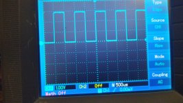
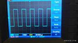
First capture is input square signal 3V./1khz taked from the same oscilloscope. (Not having external signal generator). That should be 1,5Vpp.
Second pic. is at output, Tungstenaudio mods, 20kohm. input, etc... PCB is from user Rudi here.
5Vpp at 8 ohms 3.125W
A nice10db. amplification (gain 3,3x)
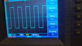
Third pic. that I shoot right now, is my own non feedback version. (And no input resistor).
Seems to have more gain: 10Vpp.
Second pic. is at output, Tungstenaudio mods, 20kohm. input, etc... PCB is from user Rudi here.
5Vpp at 8 ohms 3.125W
A nice10db. amplification (gain 3,3x)
Third pic. that I shoot right now, is my own non feedback version. (And no input resistor).
Seems to have more gain: 10Vpp.
Attachments
When checking the input RC, in first I noticed is no need to tame the gain to fit other less sensitive drivers in the speaker. R11 straight to half, so the original value 10k, for my system, fits better than 20k.
C3 value (10uF). Then after I noticed those two components form a filter of some kind. Because they balance each other. I sorry don't remember right now which one rises the highs or lows frequencies respectively, when value come down. I remember was a fun decreasing both values at once. Maybe I was lucky my preamp keep me complete delete input R11, but only in case C3 is 3,3uF.
C3 value (10uF). Then after I noticed those two components form a filter of some kind. Because they balance each other. I sorry don't remember right now which one rises the highs or lows frequencies respectively, when value come down. I remember was a fun decreasing both values at once. Maybe I was lucky my preamp keep me complete delete input R11, but only in case C3 is 3,3uF.
Joimonf,
I have kind of a full range open baffle mixture. Have a couple alnico 12 inch full ranges, but have a small tweeter for top frequencies, but also have a mid-range horn from a Klipsch Heresy
with a minimal crossover to balance the sound. The speakers are very sensitive, plenty of power plus reserve in amp amp. Some day I would like to hear some horn speakers.
Dfoulk deleting the neg feedback circuitery R12/C12 you may get good use of one of your pair 12" fullrange in outdoors. I'd like hear them in open baffle for a barbecue in the back yard!
But not the same if using three way crossover speaker, arranged as used to be, each filter in parallel.
In that case better leave R12 in place (in my system C12 silver mica 10pF not needed, adds noise)
This is better explained in the unvaluable article, firstwatt.com, 2004 year, current source amplifiers and fullrange speakers.
Turning back to the ACA matter, while I delete the feedback circuitry, I noticed a great extension in both bass and treble frequencies, mainly in bass region. I guessed, I turned ACA to a pure 'current source' as is their 'brother' amplifier F2.
I wish papa confirms.
After some fine tuning in the power supply (Ubib by Salas), today I took another hearing on R14, as tomorrow I will get quotation for the Anode choke, wanting to be certain, I set a new arrangement, free from variables, I was lucky the magical spot was in the range I expected, the new value 2k49. For my 8 ohm speaker, this is.R14, 1kohm, is critical for sound quality, and must be upgraded to maximum quality available. I heard increase sound quality using Riken resistor, then further upgrade with Vishay naked TX2352, but the definitive component here is an inductor (grid choke). I tried different values and found 2k7 to be ideal (for my 8 ohm speaker).
Jordi
For premium components, I can recommend is good sounding Panasonic FC 100uF as C4 much better than Silmic or Nichicon KZ. (Not compared to Tungstenaudio choice Nichicon series RL8). As C2 did'nt have Nichicon RNL either, but may be worth mention, that in this position prefer lower 1000uF to 470uF, preferabily Nichicon KZ over Silmic II. It may be even better panasonic FC (or Nichicon organic series -never heard).
Another minor detail, I found on the Rudi PCB, a place 1000uF (not in schemantic diagram), a local decoupling for the power supply, 1000uF in my case is too high, clogs the sound. I know other may differ as is Power supply related, but for my Ubib power supply, can't go higher than 47uF.
Another minor detail, I found on the Rudi PCB, a place 1000uF (not in schemantic diagram), a local decoupling for the power supply, 1000uF in my case is too high, clogs the sound. I know other may differ as is Power supply related, but for my Ubib power supply, can't go higher than 47uF.
Last edited:
I think C1 deserves alone a post.
Not sure if it is signal pass, but has a main role in the shunt current source. And has great imprint in the sound.
Easy to hear sound differences for diferent capacitor brand. For me first try is, as usual when checking capacitors. Try lowering the capacitance as much as possible as a rule. I set my preference back to original N. Pass value 3300uF. Better detail overall than 4700, Can't go further lower without bass wheight loss.
Here I prefer again Panasonic FC over other 'non boutique' caps I could pick in the parts bin. But since I find great sound quality increase by use of low value cap bypasses, I may guess this C1 place worth the expense to acquire top quality, you call Audio Note Kaisei, Mundorf AG+, etc.. and forget the bypasses thing.
I have a 63 volt 4700uf Nichicon Gold for my C1, by-passed with a .1uf + .01uf.
Presently am working on my refined power supply. I have made the first stage of the power inside an old Superphon amp case that I originally built the Amp Camp inside of, but never had enough room to put everything in, and got tired of everything being so darn congested. The first part has the 300VA Antek toroid with 25 volt secondaries. From the single bridge, I run each channel through a 10mH choke. I use a single bridge and parallel the secondaries because I can't get enough volts if I split the secondaries up through separate bridge rectifiers. As it is set up, the transformer is putting out around 36 volts a channel going into the chokes. That then goes into a a 27,200uf filter bank for each channel, and pops out the back at around 31 volts. I used a 3 conductor power cord to transfer that 31 volts each channel into the next case , an old B&K ST-140, that has the amp camp inside, along with a 33,000uf capacitor for each channel. I used the 3 prong IEC power connector as the interface for bringing the 30 volts in for the amp. Instead of the usual hot, neutral, and ground, I used the hot and neutral pins for right and left channel hot, and the ground pin for the neutral, and used the front panel switch to switch the shared neutral. The first case uses the regular 3 prong power connector, and front switch for power as usual.
Made some changes to the amp circuit, but will wait to hear it before commenting 🙂
followup
Had to switch the order of capacitors and choke in stage 1 of power supply to raise voltage. First bank of capacitors made up of 8 X 6800uf Vishay 80 volt caps. Right and left channels share this 54,400 uf of storage. This feeds a separate 10 mH Hammond choke for right and left, 159ZJ I believe is part model.
This affords 36 volts out no load for each channel that goes to next case that holds the amp boards, and a separate 33,000uf Nichicon cap for each channel.
Under load, it is delivering 29.6 volts. I set idle voltage at 15.2 volts.
Other changes to circuit are 234K plus 27pf mica cap for position R12.
R14 is 1.4K, and R11 is still 10K. Linear power supply is at last completely silent, using an Antek 3225, 25 volt secondaries which has the secondaries paralleled at the single bridge rectifier. Couldn't get enough voltage when separating the secondaries with their own rectifier.
Do not have a scope, but the amp has never sounded as clean. On instruments like string bass, much cleaner tones and resonances. Treble extension balanced without any harshness.
The original heat sinks very warm, but can still hold onto them for more than 5 seconds, but they are also bolted to the case heat sinks of a B&K ST-202 amp which now houses the amp camp.
A fun adventure🙂
The final step has been to unplug my preamp, and switch to a simple shunt passive with
25K pots. Though I like my FET line stage, I don't need the gain to have plenty of listening volume.
I have to say that I enjoy the fact I don't have to plug the passive in for it to work and
I don't notice any loss of dynamics, and have bass to spare.
25K pots. Though I like my FET line stage, I don't need the gain to have plenty of listening volume.
I have to say that I enjoy the fact I don't have to plug the passive in for it to work and
I don't notice any loss of dynamics, and have bass to spare.
The original Pass circuit R3/.68 and R4/.68 (parallel=.34).
Tungstenaudio raise that total value to .28 (R3 & R4=.56).
But I find a bit better results going a little further in this raising, till reach .23, by a consequence of changing one resistor .56 for a .4
Tungstenaudio raise that total value to .28 (R3 & R4=.56).
But I find a bit better results going a little further in this raising, till reach .23, by a consequence of changing one resistor .56 for a .4
- Home
- Amplifiers
- Pass Labs
- ACA amp with premium parts