So far I've set it to 30mV. The temperature of the radiator next to the transistors is 47-48 C.You're welcome @Topa41
Further it will be seen. How high can you raise the temperature?

Congretulations. You did it!...How high can you raise the temperature?...
Just leave it that way. Don't challenge fate without a good reason. At 30 mV you will have great sound. I went up to 60mV with large heat sinks but it pays-of just at high power output, but just slightly.
Have a pleasant Sunday evening.
Question!
I need to adjust the indicator board for the new amplifier, with what amplitude is it necessary to send a signal from the generator in order to understand the maximum?
Thank you.
I need to adjust the indicator board for the new amplifier, with what amplitude is it necessary to send a signal from the generator in order to understand the maximum?
Thank you.
Hello. Apparently it depends on the load of the amplifier. What is your speaker impedance? I would do so. I connected a resistor to the output of the amplifier, the value of which is equal to the impedance of the acoustics. It should be borne in mind that the power of the resistor must be sufficient (corresponding to the maximum power). I didn’t have this and I immersed a 10W resistor in water. I do not recommend heating water for a long time)). Further. I would set it to 50Hz on the generator and control the voltage at the output of the amplifier with a multimeter. 50Hz is more convenient to measure with a multimeter in the AC voltage measurement mode (less measurement error). If there is an oscilloscope, then you can apply a different frequency. Start with the minimum signal amplitude from the generator. Further Ohm's law has not been canceled. Divide the voltage measured by the multimeter by the value of the resistor. We get the current value. Multiply by the voltage value. Setting up the indicator. Something like this.
Usually, such adjustments are made on a 1 kHz signal. 50Hz is not a very low frequency for this? I have had a load for a long time, a dual resistor, 50W each.
I wrote, if there is an oscilloscope, then any frequency is possible. Including 1000Hz. Just a multimeter will not normally measure the voltage at this frequency. A normal amplifier must play from 20Hz. So...
If there are concerns, then you can not twist the amplitude of the generator to the maximum, or do it not for a long time.
We will study. It's just that earlier, to set up the equipment, frequencies and amplitude were indicated according to certain standards. In the Soviet Union, this is 100Hz, 1kHz, 20kHz basically and 0.5V. In Europe, it seems to be 0.7V. And now the equipment and 1V gives out up to 2V. That is why it is not clear on which signal it is correct to regulate this amplifier?

These are youtube jokes. He does not show Russia with the sound U2 Use VPN-(Where is the video?🤔
The problem with the low-frequency rumble did not bypass me either. 🙁If nothing is connected to the inputs or the inputs are shorted, then there is complete silence in the speakers, but if you connect something or connect two inputs with a RCA cable, then a low-frequency hum immediately appears. Until I figured out what to do about it.😡 Dartzill was silent in this regard. I removed the Dartzilla boards and installed the A60. All connections are exactly the same.
I read the documents from Hifisonix, but I didn’t understand where exactly to put the HBR resistor in the A60😒
I read the documents from Hifisonix, but I didn’t understand where exactly to put the HBR resistor in the A60😒
Connect the ground inputs of each channel through 10 ohm resistors per chassis. Don't go anywhere else. The earth from the feeder goes to the board in its place. The board is wired correctly. Since there are remote power boards, a loop can form when the cable is connected.🤔
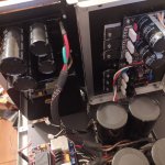
I added additional capacitors to the amplifier's power supply to reduce noise. But it turned out that the place where the conductors from these capacitors are connected to the amplifier board is very important. First I connected them in the middle of the board to the +/- 50V tracks and in the ground also in the middle of the board (I have the 16 transistor version). And I also had noise. What was my surprise when I connected the capacitors as close as possible to the power connectors of the board and to the connector for acoustics (ground). Now there is a slight rustle in the high-frequency speaker, if the ear is kept at a distance of 1-5 cm from it. And it seems to me that when I left 8 transistors per channel and replaced the Toshiba 5200/1943 ON MJL 4302/4281, the sound became more bassy, which is important with my heavy Kevlar suspensions. You can also reduce the gain of the amplifier a little by slightly increasing the value of one of the resistors. I reduced it from 30 to 20. And now the volume control on the preamp has become more like the truth (it was excessively loud at the very beginning of the range before). If interested, I'll tell you which resistor.
I have the same boards and I didn’t do anything extra with them. Everything was done with high quality and no extraneous noise. I added capacitors of 24000 per channel, more in the old case. When I built in the new one, I removed them, it makes no difference what is in the bass (30 cm speaker) or in a different range. The board with 3 pairs is wired correctly for power, look for the right place to connect the ground from the external power supply. There is a 47k resistor at the input, no need to change it. The sensitivity of the amplifier corresponds. I serve even from a dac (2v), even from a CD player, the return is the same. I think you need to look in the power supply.
As usual, Paroxod is absolutely right.Connect the ground inputs of each channel through 10 ohm resistors per chassis. Don't go anywhere else. The earth from the feeder goes to the board in its place. The board is wired correctly. Since there are remote power boards, a loop can form when the cable is connected.🤔
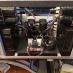
I went today to my bench, to verify this, I connected 2X24VAC transformer to the board (60+), signal generator and 400W 8Ohm dummy load. I have also connected my oscilloscope to the load.
Sinusoidal output was clean. Then I turned off the signal and have measured just the amplifier noise. The noise was below the detection level of my oscilloscope. There was the same response as I had shorted the probe. Nothing.
Then I have connected speakers with no signal at the input (shorted terminals). I have pushed my ear directly to the cone of the speaker, to practically 1 mm distance from the cone. Deadly silence. Nothing.
This indicates that the amplifier is not the source of undesirable noise. Grounding should be done properly.
This amplifier can work perfectly with the on-board power supply. (Don't be confused with the fact that I use an external power supply. That is for different reason - I'm just playing)
The only condition is proper grounding. I know there is HifiSonix manual on that subject circulating here around, but there is no need to go to such length. Mattes are much simpler. There are several simple but great posts in this thread:
Understanding Star Grounding
by our freiend Digi01. Just read posts #1, #2, #4, #5, #7 and #11. <<<= PS: Post #11 is especially important!
Simply: there can be just one connection between channels, desirably at the RCA grounds. That's all. It is possible to prove this strictly mathematically - I did that for fun by applying Kirchhoff's 1 & 2 laws on a set of equations describing two looped networks.
Have a pleasant Week End.
Last edited:
- Home
- Amplifiers
- Solid State
- A60(+) Amplifier. Build this?