Please try to stay on topic gabdx.
This is about coupling stages, RC vs IT, where bifilar winding for (only) 1:1 IT's makes sense.
Not for OT's, where the only example using bifilar winding is Macintosh unity coupling output stage.
This is about coupling stages, RC vs IT, where bifilar winding for (only) 1:1 IT's makes sense.
Not for OT's, where the only example using bifilar winding is Macintosh unity coupling output stage.
High quality capacitors are very cheap.
It is expensive capacitors which are not cheap, but in some cases they are lower quality than cheap capacitors.
ROTFL. I think you have no idea then of what best caps are. Even electrolytics. Why did they stop making Back Gates despite the fact they still are superior (if new) to any other of that type? Without going into opinions their superiority is measurable and substantial. Answer: too expensive!!! Look at the old list prices....they weren't cheap by any standard but they were better. No question about it. The only one getting close today is the Elna Silmic. Not expensive as BG but not cheap either.
Last edited:
I would like to see the plans too. <snip>
You have to pay me! Do you want to know my fee mr talker?😀
Please try to stay on topic gabdx.
This is about coupling stages, RC vs IT, where bifilar winding for (only) 1:1 IT's makes sense.
Not for OT's, where the only example using bifilar winding is Macintosh unity coupling output stage.
It is possible to get wide bandwidth even without bifilar. Actually Pieter T shared some of his experience on this as he was asked to do something with as close as possible FR but also withstanding high primary-to-secondary DC voltage differential. The latter sometimes being a limiting factor for bifilar IT's. Always a matter of requirements and trade-offs....nothing new.
OT's do not need bifilar at all for large bandwidth. It's just how much effort you want to put in it or if you buy how much money.
this is non bifilar for example:
http://www.monolithmagnetics.com/si...3 25 interstage transformer prelim rev 01.pdf
this is non bifilar for example:
http://www.monolithmagnetics.com/si...3 25 interstage transformer prelim rev 01.pdf
I think the author of that datasheet got a bit confused. For a driving impedance of 1500 ohms and 75 Henries inductance, the LF cut-off is indeed 3 Hz (This ignores the winding resistance, which raises the cutoff by about 20%. But the graph shows 6 dB down at 3 Hz, not 3 dB. But an ECC99 has a plate resistance of 2300 ohm, which would produce an LF response matching the graph. The table is ok for LF response. HF response would depend on miller effect in the driver tube - which depends on the circuit, so the datasheet figures don't count for much. (Depends on the output tube miller effect too, but they give a load of 100 pF)
Last edited:
I use these for interstage coupling: 10pcs X2-MPX Polypropylene Film Safety Security Capacitor 0.22uF 2TPO | eBay
They sound perfectly fine compared to more expensive types like Orange Drop etc, but feel free to waste money on boutique capacitors or unneeded transformers. 😀 I'm not willing to spend a hundred times more to net a <0.1% improvement.
They sound perfectly fine compared to more expensive types like Orange Drop etc, but feel free to waste money on boutique capacitors or unneeded transformers. 😀 I'm not willing to spend a hundred times more to net a <0.1% improvement.
"Every stick has 2 ends"
Agreed, but one is often sharper than the other.
feedback around a coupling capacitor increases sharpness of dynamic distortions, but decreases their impact, making recovery faster and percentage of distortions lower.
It all depends on the amount of feedback and how it's applied. As both of us know driving the grid of an output tube directly with a capacitor is a recipe for blocking distortion, bias shift, and all sorts of other evils. Attempting to correct this with feedback, especially lots of GNFB just makes matters worse.
Situations like this are very common in the tube amp world, and are one of the reasons that different capacitors can sound different in this application. Once the output tube's bias has been upset, even a little, it's distortion will increase. The recovery time should be well defined with a theoretically perfect cap, but we don't have them. A cap that has it's own secondary charge storage issues can delay the recovery time.
The essence of design of electronics equipment is optimization.
I spent most of my 41 year engineering career doing exactly that. I worked on equipment where cost was not a design factor and people's lives often depended on the stuff working.....I also spent several years in cell phone development where the exact opposite is true.
one of ways to kill several ducks by a single shot is to enclose a coupling cap before a follower, instead of before an output tube's grid......Here is what I use to drive grids of tubes
I stuck a mosfet follower in the first Tubelab product, the TSE over 15 years ago. It brought more bad responses than good ones when I first published it. People even told me to change my name to Transistorlab. Well a few people bought my boards, and some of the resulting amps made their way to some upscale audio shows.....The TSE, and now the TSE-II are still going strong after almost 15 years.
Sure there are still ardent followers of the "no sand in the signal path" "and IT transformers everywhere" beliefs, and they are entitled to their opinions. They were perfectly valid 40 years ago when most capacitors did suck, and good low capacitance mosfets didn't exist. Today wr have better caps and transformers than we had 40 years ago, primarily due to better materials, but we also have more options.
I think the author of that datasheet got a bit confused. For a driving impedance of 1500 ohms and 75 Henries inductance, the LF cut-off is indeed 3 Hz (This ignores the winding resistance, which raises the cutoff by about 20%. But the graph shows 6 dB down at 3 Hz, not 3 dB. But an ECC99 has a plate resistance of 2300 ohm, which would produce an LF response matching the graph. The table is ok for LF response. HF response would depend on miller effect in the driver tube - which depends on the circuit, so the datasheet figures don't count for much. (Depends on the output tube miller effect too, but they give a load of 100 pF)
Or you might be confused because the specs and the graph correspond to different situations. It's 3Hz at high signal. There is also some signal dependance of L despite the air-gap in particular at low level until it becomes constant. They use the dummy because tubes do have capacitance and probably they decided that graph is more representative. Using dummies is not a rule though actually no dummies is generally recommended as power triodes have typical capacitance in the 50-100 pF range. By experience the MM transformers are excellent.
Last edited:
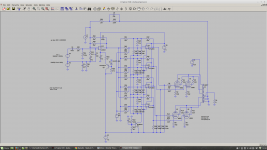
Ouput without caps
Yes its possible if your happy to replace the driver stages with and op-amp. I used an OPA453 which is powered from +5V and -73V which is enough to drive the grids of a 6550. V4 is in fact a 4 channel DAC to bias each 6550 individually. Of course removing the driver with remove that 'Valve' sound caused mainly by slew rate limiting.
Yes its possible if your happy to replace the driver stages with and op-amp. I used an OPA453 which is powered from +5V and -73V which is enough to drive the grids of a 6550. V4 is in fact a 4 channel DAC to bias each 6550 individually. Of course removing the driver with remove that 'Valve' sound caused mainly by slew rate limiting.
Attachments
Or you might be confused because the specs and the graph correspond to different situations. It's 3Hz at high signal. …...
But they didn't say that. If they meant different circumstances they should have said so. You're just making an unlikely assumption to suit your argument. Meanwhile it seems quite a coincidence that the graph actually matches what you would get if you put the specified 75 henries across the output of an ECC99. And it's standard to quote primary side inductance with the rated conditions - in this case 25 mA bias and signal comfortably inside the saturation limit. So, if low level response is not as good as high level as you claim (actually, the difference is typically not very significant), then a 6 Hz cutoff is the best you can hope for under any operating conditions, with an ECC99 driver.
Saturation: That reminds me - saturation is quoted as 140V pk-pk at 20Hz and 100V @ 15 Hz. That translates to saturation at ~40 V pk-pk at 6 Hz, and ~20 V pk-pk at 3 Hz. A 300B requires ~100 V grid swing - so you are not going to get full bandwidth at other than low level anyway. Even at 15 Hz, things are going to be pretty distorted. Overdriven transformers don't clip with flat or flatish tops like tubes. They tend to generate horrible spikes, as inductance rapidly collapses as saturation is approached.
In an important sense, you have bass bandwidth you can't use.
For reproduction off LP records, the only thing much below 50 Hz is turntable rumble, so no big deal perhaps. But with CD's, you get signal down to 15 Hz, so this transformer is not good at all.
Last edited:
Quite a controversial topic I see.
Some say the cap (and its character) is an integral part of the tube sound and if you take that away, you'll lose a part of "our sweet vacuum tubes" sound. Conversely, one should be able to construct a "magic box" with a string of RC coupled sand based buffers inside, that creates or brings back a considerable part of that sound. Oh, they already have those in the form of "tube-zillator buffering" where perhaps the RC coupling from the tube stage has as much to do with any agreeable sonics as the tube does.
Since I'm pretty sure I've only heard any tube amp with RC coupling, I wouldnt know any different. For all I know it's true, I've been set up experientially for so long (since the beginning) that this is the "sweet musical vacuum tube" sound, taking the capacitors out could ruin it. But that would be based on my own conditioning...versus something verifiable objectively - or subjectively, by another set of ears not so conditioned.
I really appreciate the sharing here, all the wonderful schematics to ponder over - and the links! Interesting to see "Steve's" site where he shows the distortions generated by various capacitor formulas, leading to (of course) PIO being the best. The old Sprague "Orange Drop" improvement in the Dynaco MKIII was really just trading off one distortion signature for another and the original "Bumble Bee" coupling caps probably actually sounded better - as long as they werent leaking. Or maybe someone was just paying this Steve fellow to say so, who provided him with some "great sounding" PIOs they're selling...
I realize the degree of capacitor distortion "signature" effects depend on where in the circuit - directly in the signal path - or in peripheral circuitry the capacitor is used. You could put a polyprop directly across the AC line entry to the amplifier - is that going to have as audible an effect as directly in the signal path? I also realize that caps will sound different with a DC bias (er, class A?), versus conducting an AC signal through.
I have to believe that if "auto-biasing" is practical, even no problem, then any balance drifting issues when using DC coupling - with warm-up, component ageing, AC line variations etc - could be taken care of by some "auto balancing" circuit that's NOT IN THE SIGNAL PATH IN ANY WAY (I like that all-caps claim). Even if you used a motor driven potentiometer to do it - not so strange in this world...
The genesis of my post arises from an impulse ebay buy of a set of Fostex FE-103en loaded in Akai cabinets. No crossover, no caps. I've never heard anything like them - too bad too; all those years... Whether this is attributable to the direct connection to the amplifier - or - solely the speaker construction itself, I dunno.
However I suspected that it has something to do with the elimination of the crossover. I've never heard an audio speaker without one - except when I was a kid playing around with a Utah 8" with a whizzer cone. As soon as Radio-Electronics taught me what a tweeter was and what the capacitor did, I was off and running attempting two-way systems using the default non-polarized electrolytics. 50 years of conditioning that "this is what a loudspeaker sounds like", what with its crossover using various formula caps in all kinds of positions circuit-wise. (Yes, I do find the inefficient series R - parallel L form of tweeter crossover intriguing)
I thought "maybe it's a step in the right direction" tube amplifier wise, hence the post.
Thanks everyone!
Last edited:
Of course, the big irony is that if you want to hear your capacitor free amplifier working, then you'll have to connect it to your speakers..... which probably have capacitors in the crossover.
The "best sounding" speakers I ever heard were Quad Electrostatics. These are mylar sheets suspended between two high voltage plates. That sounds like not much more than a large squeeky capacitor to me!
kind regards
Marek
The "best sounding" speakers I ever heard were Quad Electrostatics. These are mylar sheets suspended between two high voltage plates. That sounds like not much more than a large squeeky capacitor to me!
kind regards
Marek
The question I have is why do you wish to remove the coupling caps. Modern non electrolytic caps such as polypropylene MK2 are completely blameless in an audio amp and won't impart any colour to the sound. OK ceramics of high values are to be avoided. Good caps are also very cheap.
Inter stage transformers could be OK but they need to have good mutual coupling between primary and secondary. Otherwise they can add group delay to the the signal which makes applying negative feedback more difficult as the phase margins will be lower. They can also pick up hum from the mains transformer.
The biggest offenders are the valves themselves. The driver stages often don't present a low enough output impedance to overcome the capacitance of the grids on the output stages. Try putting 10kHz sinewave through your favourite amp and look at the output on a scope (use a dummy load). You may be surprised at what you see! You could argue the harmonics are not important. However if you were to put say 9kHz and 10kHz together then the ear will hear the 1KHz IM distortion even if its quite low.
Interesting topic.
Sure there are still ardent followers of the "no sand in the signal path" "and IT transformers everywhere" beliefs, and they are entitled to their opinions. They were perfectly valid 40 years ago when most capacitors did suck, and good low capacitance mosfets didn't exist. Today wr have better caps and transformers than we had 40 years ago, primarily due to better materials, but we also have more options.
What is funny, I could not find such people among real audiophiles who used to own many different very expensive setups. They want better sound, believe own ears, and do not care about what components are in their amps. Who believes in such BS, are wannabe audiophiles who never owned audiophile quality systems. Most of them try to build, or order to build, what they believe to be an audiophile quality equipment, actually trying to get all cheaper than they would pay for available on the market systems. We see lot of them here on the forum. Some of them contact me with offers like "I will pay you if you design and build an amp that has such tube set, uses such capacitors", and so on... And all of them want to pay for my nearly impossible work to use given tubes that they prefer even less than for mass production amplifiers. It explains.
@Tony,
My friend pieter t tells me it is nothing special really: bifilar windings.
But Tony, as a winder yourself, you should know that...
no, i do not know, and so i ask...
What is funny, I could not find such people among real audiophiles who used to own many different very expensive setups. They want better sound, believe own ears, and do not care about what components are in their amps. Who believes in such BS, are wannabe audiophiles who never owned audiophile quality systems. Most of them try to build, or order to build, what they believe to be an audiophile quality equipment, actually trying to get all cheaper than they would pay for available on the market systems. We see lot of them here on the forum. Some of them contact me with offers like "I will pay you if you design and build an amp that has such tube set, uses such capacitors", and so on... And all of them want to pay for my nearly impossible work to use given tubes that they prefer even less than for mass production amplifiers. It explains.
people with money, they can buy anything....
When good Class D amplifiers started to appear, some companies chose to include a large unneeded heatsink because audiophiles expected there to be one.
The question I have is why do you wish to remove the coupling caps. Modern non electrolytic caps such as polypropylene MK2 are completely blameless in an audio amp and won't impart any colour to the sound. OK ceramics of high values are to be avoided. Good caps are also very cheap.
Inter stage transformers could be OK but they need to have good mutual coupling between primary and secondary. Otherwise they can add group delay to the the signal which makes applying negative feedback more difficult as the phase margins will be lower. They can also pick up hum from the mains transformer.
The biggest offenders are the valves themselves. The driver stages often don't present a low enough output impedance to overcome the capacitance of the grids on the output stages. Try putting 10kHz sinewave through your favourite amp and look at the output on a scope (use a dummy load). You may be surprised at what you see! You could argue the harmonics are not important. However if you were to put say 9kHz and 10kHz together then the ear will hear the 1KHz IM distortion even if its quite low.
Interesting topic.
i have stromberg carlson tube amps and a scott lk38 that used ceramic disks as coupling caps and yet sounded so good, why is that?
No. You have been reading too many audio websites and reading too few electronics textbooks.
If you want to improve a tube amp then the first thing to get rid of is the tubes. Then ditch the transformers. After that it is difficult to decide whether to get rid of the resistors or capacitors - maybe the caps should go. Finally, some would want to get rid of the wires.
The reason you don't see tube circuits wired like modern opamps is that nobody has invented opposite polarity tubes using positrons instead of electrons.
That's right. There are no PNP or P-channel tubes, so the bias keeps climbing stage by stage to ever higher positive voltages. The neon lamps are "Zeners", an attempt to DC offset the bias voltage back down towards the negative supply, but neon lamps are not very linear compared to capacitors, so there is no point unless you want a DC amp and distortion is not important. Coupling caps in tube amps are usually in the nano-Farad range, ie ceramic or mylar which are very linear, much cleaner than tubes or transformers. The only caps that may be a problem are cathode decoupling caps, which can be eliminated with negative bias voltages.
Tubes are "Steam Punk" and it amuses me that many new tube amps use LM317 or similar semiconductors to make them work. Personally, I have no space for stereo components anymore. Even desktop computers are becoming extinct and laptops and any kind of linear amplifier are not be far behind.
But the biggest problem with recorded music is the lack of great musicians. No one cares about audiophile grade sound because there is no high quality new music.
No one cares about audiophile grade sound because there is no high quality new music.
Maybe you are too old to find it.
- Home
- Amplifiers
- Tubes / Valves
- A Tube amp without coupling capacitors? Possible?