I have not heard of anyone using a safety cap as a coupling cap. Can you elaborate on benefits aand drawbacks and how you decided to try them in the first place?Interesting scope trace for 100kHz through an IT.
Here's my scope trace of 100kHz through a Carli 1uF X2 MKP safety capacitor which I use for coupling.
Also included is a trace at 1MHz.
Not bad for a 50 cent capacitor...
No, it is not. Can't believe people still believe in that. It is only CAPACITIVE of you use it like a capacitor.
Transformer wired, the potentials at the secondary will be the same as the ones primary and no capacitive currents flow.
You are correct in that no "common mode" current flows thru the bifilar capacitance, but differential voltage most certainly does couple capacitively along with the distributed L component, which is what counts. You can pull the magnetic core out and it will still work for MF to HF.
Putting thicker insulation on the bifilar wires will also degrade the performance. The bifilar configuration does greatly improve (reduce) the leakage inductance, for good HF performance. The 1:1 case keeps the voltage across the distributed bifilar capacitance constant if the core is present and well coupled. So in that ideal case the C component would not conduct AC current. Never the less, the C and L coupling components are in parallel. One could just as easily say the C component does all the coupling and the L component sits idly by as all the load current goes thru the C.
Finite wire diameter causes the distributed L coupling (which is in air or dielectric) to have finite coupling impedance, instead of zero, so some voltage differential developed across the distr C is inevitable. You simply have two low impedance couplings in parallel, and the lowest reactance path will take the bulk of the transmitted current.
Ideally the bifilar L would prevent current thru the distributed bifilar capacitance from occurring, but practically, the outer parts of the winding will have leakage L relative to the core, allowing some divergence of voltage between the wires, which the distr. capacitance will continue to keep in lock fortunately. Just as in the no core case. Wire resistance inevitably causes some voltage divergence as well if there is current. (always some magnetizing current + any load current)
Last edited:
it is all about the money then....You have to pay me! Do you want to know my fee mr talker?😀
It is possible to get wide bandwidth even without bifilar. Actually Pieter T shared some of his experience on this as he was asked to do something with as close as possible FR but also withstanding high primary-to-secondary DC voltage differential. The latter sometimes being a limiting factor for bifilar IT's. Always a matter of requirements and trade-offs....nothing new.
OT's do not need bifilar at all for large bandwidth. It's just how much effort you want to put in it or if you buy how much money.
this is non bifilar for example:
http://www.monolithmagnetics.com/si...3 25 interstage transformer prelim rev 01.pdf
I have not heard of anyone using a safety cap as a coupling cap.
I use them routinely. Great caps.
I use them routinely. Great caps.
sssshhh.....😀 that is supposed to be a secret....😀 now the prices of those things will rise......
sssshhh.....😀 that is supposed to be a secret....😀 now the prices of those things will rise......
Let it be, I already have several bags. 😀
I've looked at "safety caps" for years as coupling caps, have a pair in my Sophia amp now, because I ruined the Sophia branded capacitors by soldering near them... They are only 250V, so I have them on the cathode side of the cathodyne phase splitter. The two remaining good Sophia caps on the plates.
These caps were used in the AC input filters of switching power supplies to minimize conducted emissions. They're called "safety" because they typically have markings reflecting various world wide safety agency approvals for direct connection to AC mains use. These agencies are concerned with things like leakage current out the ground prong and since these caps as used in the filter topologies determine that more or less, the safety agancy wants a damn good cap - reliability wise - in that spot. Otherwise, they're just a good quality cap, many are polypropylene, so it's understandable they'd make a good coupling cap for audio.
My take on a previous question about why ceramics could sound as good, is that they probably have a lot of DC across them. Caps generally are more linear with significant DC bias. Other than that, I have no explanation how ceramic caps used in an audio stage coupling circuit could sound as good.
Last edited:
with metalized polypropylene used, who can complain?
Who? Unhappy boutique dealers. 😀
Just because an amp has low distortion does not mean you will like the sound. You may prefer the amp with distortion. That's what guitar amps are all about. On a well designed amp ceramics may be fine, or they well be producing some 2rd harmonic which makes the amp sound 'sweet'.
Maybe you should swap then out for polypropylene, the distortion will be lower but that nice sound may vanish.
In my books a hi-fi amp should be blameless in that the output should be a copy of the input. However that's quite tricky with valve amps, and we would all be buying modern amps with .0002% distortion.
However its a challenge to make a valve amp with low distortion which what makes it interesting. The technology is from a age when I was a kid. Plus they glow, look like a beast and there's a real sense of danger building them.
Not sure that is true. What happens is that some 3rd order distortion becomes 2nd order distortion, which may sound better to some people.jjasniew said:Caps generally are more linear with significant DC bias.
Consider a cap with dominant 3rd order distortion (e.g. a non-polar cap). It has signal voltage Vsig across it. It will generate a current which includes a Vsig^3 term, which has IM and harmonic distortion. Third harmonic will be 1/8 Vsig^3.
Now add a DC bias, so the voltage is Vsig+Vdc. The current now has a term (Vsig+Vdc)^3, which is Vsig^3 + 3 Vdc Vsig^2 + 3 Vdc^2 Vsig +Vdc^3. So in addition to our 1/8 Vsig^3 third harmonic we also have 3/4 Vdc Vsig^2 second harmonic. In most cases Vdc will be much higher than Vsig, so there will be much more second than third (ratio is 6 Vdc/Vsig). The second harmonic may mask the third, although IM will not get this advantage.
DF96's reasoning is essentially correct, though of course the amount of 3rd order distortion at zero bias is not necessarily anywhere near as bad as 1/8.
What is important to note is that in a competently designed amplifier, the coupling capacitors will have very little signal voltage ACROSS them throughout almost all the audio band. Except for bass frequencies, the signal voltage ACROSS the caps is negligible. And if its negligible, any distortion products must be negligible.
But at low bass frequencies this is not the case. Clearly, if a cap rolls off 3dB at 30 Hz, then at 30 Hz the signal volts across the cap is the same as the voltage applied to the next grid. At 300 Hz the cap signal volts will be 1/10th and so on.
It happens that the human ear is most sensitive to distortion at mid range frequencies, and the mechanism of the ear masks frequencies close in to a dominant tone - eg if you intermod 30 Hz with 1 kHz, you get 1 KHz (the wanted signal), plus 970 Hz and 1030 Hz (distortion). It is very difficult to hear these tones, unless they are strong enough to cause noticeable vibrato.
If tube amplifier has global negative feedback, the bass roll-off should be set at one point only, by a coupling capacitor. Otherwise it won't be stable due to phase rotation. This also means that distortion in the output transformer will be low and effectively reduced by the feedback, and distortion in all other capacitors will not be audible, because their roll-off is at lower frequencies than the deliberately chosen dominant cap. That cap can cause bass distortion because it plays a dominant role and must be a linear type. Certainly not a ceramic type.
Anything with an iron core in it will (often severely) distort frequencies around its low frequency roll-off, and there is no getting around that, except by having a big air-gap, which makes the whole thing rapidly more expensive, big, and heavy.
In cheap amplifiers, record players, and radios that were mass produced in the tube era, getting low cost meant that the bass roll-off had to be set by the output transformer, and all capacitors rolled off at lower frequencies. Big caps were/are very cheap compared to the smallest transformer. The result was stability but quite a lot of bass distortion. But cheap speakers in those day had a lot more bass distortion.
The rules of thumb for stability in high quality amplifiers in the LP record days is that the dominant cap should roll of at 50 Hz or lower, the output transformer 3 to 5 times lower (10 to 16 Hz) and all other caps in coupling, screen, and cathode bypass at least 5 times lower. Now we have CD's there is a realism advantage is scaling the whole thing lower.
If the amplifier does not have global feedback, stability is not an issue. But the bass roll-off should still be set by a single, good quality capacitor, NOT a transformer or choke, as otherwise bass distortion will occur and excessive phase rotation will stuff up stereo imaging.
Any capacitors in a tone control stage will have high signal voltage across them and mid band frequencies. Therefore any tone control stage MUST have caps chosen for linearity, and the stage should be as early in the chain as possible, cognizant with noise. RIAA equalization caps should be linear types for the same reason, but as signal levels in RIAA stages are generally low, there isn't normally a problem.
Now, I suppose "45" will pop up again and say I talk too much, but I note that several contributors here have restated what I said in my earlier posts.
Last edited:
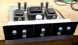
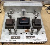
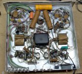
i have stromberg carlson tube amps and a scott lk38 that used ceramic disks as coupling caps and yet sounded so good, why is that?
I got one like this at a flea market for $10 with the intent to strip it for it's tubes and transformers. I fired it up and was quite surprised that it worked and sounded pretty good. I think I added one or two cheap electrolytics in the power supply to clean up some faint hum. I never did get the phono stage working right, but the power amp was used with my PC speakers for a year or so before I sold it. Sometimes a combination of all the "wrong" parts can sound quite good. Blind luck, or serious engineering? Who knows.
I worked in cell phone design during the time when the world went through a serious tantalum shortage. We were trying to design out all of the tantalum caps and replace them with ceramic.
The ceramics of the day were junk. Most were highly piezoelectric, bilaterally...vibration made voltage, but varying voltage made sound. These were early TDMA phones where the transmitter is pulsed on and off at an audio rate, and the transmitter drew about an amp of current. The phones ticked and buzzed so much that they were not usable.
Fortunately several ceramic cap suppliers were developing non-piezoelectric high K ceramics. These solved the problem in phones which were the intended market, but this technology has found its way into nearly all of today's ceramic caps. The capacitance VS voltage and C VS Temp curves are often somewhat worse than in the past, and vary with the type of ceramic used. One must study the spec sheet carefully before using these in an audio application.
Most of us avoid sticking ceramics in our tube amps, but look under the hood of your favorite DAC or CD player.
Attachments
I have not heard of anyone using a safety cap as a coupling cap. Can you elaborate on benefits aand drawbacks and how you decided to try them in the first place?
No drawback i can see. Benefit is getting a metalized polypropylene cap for a low price. Not only are they cheaper than the polyester caps I used in my first build, they work better, too.
Sometimes a combination of all the "wrong" parts can sound quite good. Blind luck, or serious engineering? Who knows.
Very true. I have an old Philips application manual that describes how to deliberately select a chain of slightly non-linear components so that the phase of low order harmonics occurs in opposite phase, and so cancel out.
Only a technique to improve the sound in low cost equipment though.
Never forget that what is one man's meat is another's poison. As has been stated many times, some people LIKE distortion - and the corollary to that is that some folk like certain types of distortion. So if an amplifier with ceramic caps sounds good to you, fine. By all means enjoy it. But don't be surprised if others disagree.
The ceramics of the day were junk. Most were highly piezoelectric, bilaterally...vibration made voltage, …..
Here in Australia, we used to see "Redcap" ceramics used as bypass caps. They were I think made by Ducon, known for shonky products. Redcaps were popular due to low cost and high capacitance in a small volume - and notorious for being pretty good microphones.
On the other hand, some well respected manufacturers (mainly American) used ceramic caps in coupling (and screen bypass applications). They did that because they were far more reliable and long lasting compared to paper dielectric types, which tended to go leaky. Leakage is a disaster in tube plate-to-grid use. They were not microphonic and were used where distortion would not be a problem (see my previous post for reasons why this can be so).
I too have some old radio station equipment, American 1954 vintage that has original ceramic caps, and they are still perfectly ok. AM studio standard though - not really hi fi.
Last edited:
Most of us avoid sticking ceramics in our tube amps, but look under the hood of your favorite DAC or CD player.
The move to surface mount parts 30 years ago pretty much forced the use of ceramics. Non-ceramic dielectrics were simply too big and too easily damaged by close-in soldering.
https://www.edn.com/Pdf/ViewPdf?contentItemId=4426318 has some spice models for the non linear capacitance verses voltage for 10n and 22n X7R ceramics showing the distortion in a op-amp filter.
** "Non-ceramic dielectrics were simply too big and too easily damaged by close-in soldering."
I have some surface mount film caps - they just melt when I try to solder them in place... (I recently bought a Metcal soldering station for $75 at a yard sale, maybe I should try again with that)
How about the modern so called "MLC" ceramics? They're probably all very low voltage, meant for Intel cpu chip carrier local decoupling...
Regarding music, what modern group would have lyrics like (below) - along with top notch musicians, recording fidelity and an actually enjoyable melody, that stands up to repeated listening?
This is for me
The essence of true romance
Sharing the things we know and love
With those of my kind
Libations
Sensations
That stagger the mind
Last edited:
Regarding music, what modern group would have lyrics like (below) - along with top notch musicians, recording fidelity and an actually enjoyable melody, that stands up to repeated listening?...
Steely Dan were outliers even in their day. If you are comparing them to what is heard in popular formats in the 201x years, your comparison is invalid. At the same time the Dan were writing and recording, the Bay City Rollers and Nolans were hugely popular - lets not pretend that all music, or even the majority of popular music, from the days of our youth was high quality and timeless.
/OTrant
- Home
- Amplifiers
- Tubes / Valves
- A Tube amp without coupling capacitors? Possible?