I came across this old BBC video, when the video got to 13 minutes, I had to laugh, as it reminded me of the good old days before DML'S 🤣
Steve.

Excellent! Thanks a lot Steve!I came across this old BBC video, when the video got to 13 minutes, I had to laugh, as it reminded me of the good old days before DML'S 🤣
Steve.
Christian
Christian,I hope some simulations will be able to give some hints in order to decide the best type and locations of mount points in order to fulfill this "requirement" to make a robust (or at least not weak) and nice looking panel.
I have also been thinking about and exploring ways to support a panel in a way that "mimics" a free panel, but is more robust and practical than just hanging it, plus avoids the problem of vibrations of the hanging members, and also provides the opportunity to provide support for the exciter. As you know, I have doubts about any true benefit of the "free" panel (other than simplicity of construction), over a well damped perimeter mounted panel, but it is an interesting technical exploration, in any event.
Originally, my thought was to use only three mounting points (the minimum to define a plane), using very soft foam to minimize any restraint. Also, I thought that the mounting points should avoid the perimeter, since virtually all the modes of a free plate have antinodes along the perimeter. Also, I thought the mounting points should be in an irregular pattern, to minimize the impact on any given mode. And finally to avoid mounting points near the exciter. But after trying many such mountings, they all suffered from ringing at one frequency or another. So I abandoned that approach.
But I recalled that hanging the panel from the centers of two adjacent sides helped minimize ringing. For example, these two spectrograms compare hanging from two points along the same edge (first images), vs. hanging from the center points (second images). Clearly, there is less ringing in the second mounting, presumably because it inhibits some of the modes most prone to ringing.


Taking inspiration from the second hanging method, and playing around a bit, I found that mounting the panel at these five points (using 18 mm squares of Poron foam) provided interesting results. Ringing isn't eliminated (still some at 60 Hz), but it's much better than the first "hanging" case. I have to admit that it is about the best sounding of any "free-ish" panel that I have tested.


And here's a comparison of a few impedance curves to provide some perspective. On top is the case of hanging from two wires on the same side, probably the worst case of ringing. The middle curve is with the "five points" mounting, and the last is for mounting with Poron foam around the entire perimeter. The "five points mounting" seems to provide very strong damping at low frequencies, but at high frequencies, the "five point" looks a lot more like the "free" (hanging) panel than the damped (Poron surround) panel.

I should note for the record that all these results are using a 2.1x584x406 mm cf/balsa sandwich panel, and a VT25-4 exciter mounted at 0.4/0.4.
Eric
Hello Eric,I have also been thinking about and exploring ways to support a panel in a way that "mimics" a free panel, but is more robust and practical than just hanging it, plus avoids the problem of vibrations of the hanging members, and also provides the opportunity to provide support for the exciter.
Thank you for your post. It is fully in what I am considering now.
Where to start..?
Maybe by this picture:
It is from the current status of my FDM simulation script. Frankly, I don't know up to which level this script is able to simulate a panel. What we know currently is its outputs about modes make sense and are closed of FEM simulation. I have implemented the electrical impedance, the SPL in a half space (like the SPL from PETTaLLS) and just few days ago the SPL of an open back panel but also a tentative to find possible suspension points.
On the left of the picture is a view of the panel simulated. Here a free edges 300x420mm with something suppose to be a polystyrene and a DAEX25VT at 0.4/0.4.
The 2 other plots are a tentative to see what are the possible suspension points. It is the sum of the speed at each points (blue dots on the left) above a certain frequency (200Hz). The points with the lower movements (or better to say lower contribution to the SPL) are the darker one.
Why 200Hz? It is because if there is a compromise to be done, better is to alter the response below this threshold than above.
As you mentioned, the edges are anti-nodes (light blue). There are even more movements at the corners (yellow to red). It is maybe the reason of the advice to round them.
There is no point of zero speed so any tentative to hang the panel should change the behavior somewhere in the FR.
But what appear from this picture is some points not far from the edges have the minimum speed. I haven't tried for now to confirm it with PETaLLS...
The plot on the right is the same with the minimum speed points set to 0 (black dot) and the points just above set to give white dots.
2 small areas appear at about 10% from the corners far from the exciter.
As I am more working on the script currently, I haven't tested them. From a simulation with those points fixed, the FR was changed more than expected. If I think those areas are a good information, nothing says the simulation is right about the FR.
If you are interested, fill free to add this to your tests.
In addition to be elements in the research of suspension points, your test cases are excellent inputs for simulation.
Is the CF/balsa poron of this panel the same for the directivity tests? I have in the paper about directivity 2 coincidences frequency: 5300 and 15000Hz.
Could you remind me its areal mass, how the stiffness are oriented according the edge lengths?
A bit more challenging would be to evaluate the stiffness of your poron pads. I am in the same idea than you that fixed points will probably not do the job. Better would be to have some soft points able to maintain the panel without restricting to much the movement.
This leads me to an other idea... Those days, I have been laying slabs in my garden. Below I use geotextile (polypropylene fabric?). It might be a possible material to make custom noiseless (? to be tested) hanging solution.
Christian
Great progress Christian.It is from the current status of my FDM simulation script.
Yes, that's good evidence that your FDM model is working. The corners are antinodes for virtually every "free" mode, so it makes sense for them to be "yellow to red".As you mentioned, the edges are anti-nodes (light blue). There are even more movements at the corners (yellow to red).
That is interesting. I was wondering myself about where the minimums would be. I ws inclined originally to try areas closer to 20% from the corners, rather than 10%, but I was really just guessing.2 small areas appear at about 10% from the corners far from the exciter.
Yes, still that panel, although I plan to make a similar one soon but about half the thickness, so the 2 coincidences should be about doubled then.In addition to be elements in the research of suspension points, your test cases are excellent inputs for simulation.
Is the CF/balsa poron of this panel the same for the directivity tests? I have in the paper about directivity 2 coincidences frequency: 5300 and 15000Hz.
Could you remind me its areal mass, how the stiffness are oriented according the edge lengths?
But for the current panel, the moduli are about 25 GPa and 23 GPa in the length (584 mm) and width (406 mm) directions, respectively, with an areal mass of 0.945 kg/m2 (450kg/m3 x 2.1 mm).
True. However, despite my intention that they not be "fixed" points, I think they turn out to be nearly fixed. If I model the plate with FEA and assume them to be fixed points, the model predicts the modal frequencies pretty well. So, while the pads feel very soft, they still don't move much.A bit more challenging would be to evaluate the stiffness of your poron pads. I am in the same idea than you that fixed points will probably not do the job. Better would be to have some soft points able to maintain the panel without restricting to much the movement.
Eric
Good Timing Eric,
Interesting findings.
I have been meaning to ask if anyone has experimented with 'tuning' a panel by having the suspension at certain points around the perimeter, I know Leob clamps his PA panels with blocks at certain points and my best sounding home panels I did something similar with the panel held between 25mm long 9mm thick HPDM foam at points rather than full surround. I used trial and error to find better places for the pressure/damping.
I still haven't played with Pettals so not sure if this would be helpful but it would be nice to be able to predict the best places to damp the perimeter rather than full surround.
Joska
Yes good timing Joska!I did something similar with the panel held between 25mm long 9mm thick HPDM foam at points rather than full surround.
What are the positions of those pads on your panel?
PETTaLS doesn't offer such possibilities in the current free version.
Christian
Hello Eric.
Thank you for confirming that my weight points which can also used as mounting points are correct.
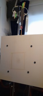
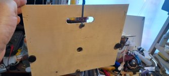
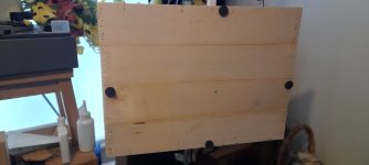
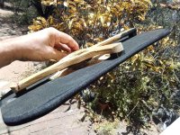
These are a few old pictures of some of the panels I have created using weights or mounting points to improve the frequency response and sound of the panels .
Notice on the first three small crate ply panels that the weights are at the first 4 reflection points.
Note, that the center point is the exciter mounting point.
If the exciter is used off centre then these points must be moved too.
This is very important.
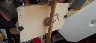
In the last picture I think this was a square fluted panel of 2ft square.
You can see that these positions are different for this panel.
This is all done by looking at the frequency response as I touch different points on the panel surface.
This is very easy on small panels, but larger panels are more complicated and complex.
My original 3ft x 2ft rigidity mounted ply panel from about 14 years ago had about 5 or 6 AA batteries stuck to it using blu-tack, but now, all but one has fallen off.
These were also at good random mounting points on that panel.
I might have some pictures on the AudioCircle forum of this but not on my phone.
I have now, been going on about these points on my panels for years now and am happy that someone has finally taken notice.
I have said many times that randomly placing weights, foam , or any other type of mounting onto the panel is like pinning the tail on a donkey while blindfolded.
They must be in the correct places or it will not look or sound correct.
Placing one weight in the wrong position could ruin everything.
Steve.
Thank you for confirming that my weight points which can also used as mounting points are correct.
These are a few old pictures of some of the panels I have created using weights or mounting points to improve the frequency response and sound of the panels .
Notice on the first three small crate ply panels that the weights are at the first 4 reflection points.
Note, that the center point is the exciter mounting point.
If the exciter is used off centre then these points must be moved too.
This is very important.
In the last picture I think this was a square fluted panel of 2ft square.
You can see that these positions are different for this panel.
This is all done by looking at the frequency response as I touch different points on the panel surface.
This is very easy on small panels, but larger panels are more complicated and complex.
My original 3ft x 2ft rigidity mounted ply panel from about 14 years ago had about 5 or 6 AA batteries stuck to it using blu-tack, but now, all but one has fallen off.
These were also at good random mounting points on that panel.
I might have some pictures on the AudioCircle forum of this but not on my phone.
I have now, been going on about these points on my panels for years now and am happy that someone has finally taken notice.
I have said many times that randomly placing weights, foam , or any other type of mounting onto the panel is like pinning the tail on a donkey while blindfolded.
They must be in the correct places or it will not look or sound correct.
Placing one weight in the wrong position could ruin everything.
Steve.
Attachments
something like this ...use only three mounting points (the minimum to define a plane), using very soft foam to minimize any restraint.
Attachments
By curiosity and because it is one goal of my FDM script to evaluate point mounting, added mass, I modified the script to add 4 5g mass at the edge points.These are a few old pictures of some of the panels I have created using weights or mounting points to improve the frequency response and sound of the panels .
Same panel as in my previous post:
As expected, the added mass are the points of the lowest speed.
More interesting is that I have implemented a function that evaluate how smooth is the on axis frequency response. It works for now on the half space response (as if the panel was radiating from a wall with no effect of the rear wave) and would be probably subject to change... So the interesting result is the added mass panel has a better "smoothness figure".
Too early to make conclusions but very encouraging as each time calculation approach and experience show the same way.
Steve, a AA battery is maybe something like 20 to 25g (23g the one I have). What is the weight of your additional edge mass?
@Veleric
As a follow up on the idea to use geotextile... The frequency resonance of a string is linked to the tension and its linear mass. When a panel is hanging without spine, the tension comes from the panel plus the exciter weight and the string section. Using a ribbon should reduce the resonance (larger section, higher linear mass) enough to have it out of the expected frequency range?
With a spine, the tension will be even lower (no more exciter weight).
Hello Christian.
The batteries were used on a 3ft x 2ft panel that had the edges firmly attached to 4cmx6cm wood frame.
The batteries were placed inside the frame area at various points.
Using light weights in these positions would have made little difference.
The weights depends on the weight of the panel itself.
You would not use the same size weights for an eps as you would for a 5mm ply panel.
Also what would be best for the sound , a rigid mounting a soft mounting or something like rubber or mastic, either reflective or absorbing.
I use these points to either fill in the large dips I the response in the 100hz to ,let's say 300hz area.
But this can also affect the sound of the panel overall.
This picture is one I posted on this forum in September 2022 with a recording of the sound of the panel changing when I placed my fingers in these different positions while playing pink noise.
This is a small cc panel , so the edges are the best places for these positions.
This shows why it is so important to place the weights in the correct places for best sound quality.
Steve.
Attachments

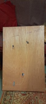
Hello Steve,This picture is one I posted on this forum in September 2022 with a recording of the sound of the panel changing when I placed my fingers in these different positions while playing pink noise.
I remember very well this. As I saw in your videos the same type of magnets, I just ask to have an idea of their weights as a kind of starting points. For sure the value is link to the panel material.
Christian
Hello Christian.
The batteries are about 25grm plus the blu-tack used to attach them.
I tried to find the positions of the batteries on this panel, I could only be sure of these 4 positions in the photo.
The magnets weigh about 8grms plus blu-tack.
I have found it much easier on thin panels to use two magnets , one on each side of the panel, so that I can slide the magnet one side and the other magnet will follow.
When a good position is found I just leave it there, then apply two more magnets and do the same again until I am happy with the response and sound.
On small panels I sometimes use old small button batteries which are much lighter.
Steve.
Attachments
So-called "laser ply" can be found in thicknesses down to and below 2mm, but so far I haven't found anyone selling it in the size I want; and vendors want to sell multi-packs rather than one or two pieces. In an earlier post I mentioned some aircraft-supply places that will sell single pieces in the 24"x24" size range. And here's another source: https://makerstock.com/products/thi...49SleF-YlLAzyQy0nLSfUx&variant=39686848839777. They also have .6, .8, 1, and 1.5mm plywood to play with, if one is so inclined.
Their pricing is a bit more than the aircraft-materials suppliers but I haven't gone so far as to determine their shipping costs.
The two 1/8" thick birch plywood panels I made from stuff I found at Lowes Hardware sound pretty good, particularly after applying equalization via camilladsp, but my FR testing has shown that their un-EQ'd responses in the 50-200 Hz range are significantly different -- possibly due to the fact that I bought the two panels on two different visits so their physical properties are different -- or perhaps because I also applied the surface finishes at different times and didn't exactly replicate the process for both of them.
In retrospect it probably would have been better to buy both panels at the same time and also apply the surface finishes at the same time. Starting with a single 2 x 4 (foot) panel, finishing the whole thing and THEN cutting two pieces to their final size would be best of all.....but not everyone can do this.
A Good Find indeed, not just for the Overall Thickness of the Panel, but also for the Tier Sheet Thickness that is the structure for the panel.
3 Plies to make up a Lamination of a overall thickness of 0.8mm - 1.5mm.
These Panels Tiers are between 0.25mm and 0.5mm, which makes the notion for sanding back a sheet local to the where the exciter mounts and increasing the sheet flexion local to the mounting a not too daunting task.
The increased flexion could prove to be attractive on such a Thin / Lightweight Panel.
As the opposite to the above is typically witnessed being adopted, where an increased in depth Panel is produced local to the exciter mounting point. This methodology is more common in use for Exciter mounting. It can still be adopted once the exciter mounting point with a decreased in thickness Panel has been experienced in use.
From the same supplier is also Acrylic at 1.5mm Thickness, with approx' 350Kg increased weight for the Cubic Metre, in panel sizes the 300ish Gram? difference per m2 won't be too much of a concern.
1.5mm Plywood 1100g/m2 vs 1.5mm Acrylic 1350g / m2.
It seems to me that plywood is going to nearly always if not always be just a bit different from sheet to sheet even if cut from the same panel, just the nature of the wood it is made from, different densities throughout the area of each layer. It would be best if no knots, layers pealed from the same depth of the same log, etc would help. Like buying matched pairs of speakers, doing the same with matching panels of plywood seems the best way to go.
----------
I love the idea of using plywood as it can be finished to look very nice and I prefer an organic material over others whenever possible.
Rick
----------
I love the idea of using plywood as it can be finished to look very nice and I prefer an organic material over others whenever possible.
Rick
It's possible that structural requirements for aircraft plywood might result in higher-quality panels, compared to stuff that's mostly meant to look good on the surface. However, is that same requirement suitable for DML panels? I don't have a clue. A list of specifications of the right type would help. It's likely that kind of info will only come from mfrs that make aircraft-quality plywood. If it's available at all.It seems to me that plywood is going to nearly always if not always be just a bit different from sheet to sheet even if cut from the same panel, just the nature of the wood it is made from, different densities throughout the area of each layer. It would be best if no knots, layers pealed from the same depth of the same log, etc would help. Like buying matched pairs of speakers, doing the same with matching panels of plywood seems the best way to go.
More plys might average things out, so thicker panels might be less variable -- but, based on my findings, that's a big maybe. Lots of variables in play here!
When it comes to Plywood Structure, the Grain Orientation between Tiers is what creates the improvements in Flexion.
An In Line Orientation will produce a Board that has less resistance to flexion, hence In Line id usually a Material to be formed into a shape through moulding.
A Cross Grain Orientation increases stiffness, reduces flexion.
What is seemingly not understood, is if a 3mm Thick Panel with In Lane Grain or Cross Grain as the structure, is able to produce sound that is discernible from each other and if one Structure is an improvement as a Panel material over the other.
- Home
- Loudspeakers
- Full Range
- A Study of DMLs as a Full Range Speaker