How think was the panel? Size and thickness ? Can you show a FResponse without EQ ?I decided to test a different strategy with respect to exciter placement than I have ever tried before. The idea was to position four identical exciters at the 0.33/0.33 locations of a simply supported panel. The exciters would all be driven in-phase with each other. This arrangement would drive the fundamental (1,1) mode very effectively. However, because the 0.33 positions are at nodes of the (1,3), (3,1) and (3,3) modes, none of those modes should be driven. Also, since all (even, even) and (even, odd) modes are all anti-symmetrical wrt one (or both) axis of the panel axes, none of those modes should be driven either. So, the next mode driven above the (1,1) mode would be the (1,5) mode.
The thought was that in the low frequency region, where the modal density is low and the frequency response is lumpy, driving only the fundamental might result in a smoother frequency response in that region.
For this test I used one of my carbon fiber skin/balsa core panels that is mounted in a frame using Poron 92 foam all around the perimeter. This mounting provides edge constraint that is close to "simple" supports and provides high perimeter damping. The exciters were DAEX25VT-4.
View attachment 1413032
I was happily surprised to find that it actually worked quite well. The impedance plot directly below shows a peak at low frequency (27 Hz) corresponding to the magnet resonance of the exciters. The next peak at just over 100 Hz is the panel fundamental. The big gap between the 100 and 600 Hz confirms that no other mode is substantially driven until about 600 Hz, approximately where the (1,5) ought to be, based on my FEA model of the panel. So this result seems to confirm that my basic objective of driving only the 1,1 mode over the lower frequency range was achieved.
The frequency response was pretty good too. About as good or better than anything else I have built. Sounded great on a live track of the Eagles "Hotel California", and Dire Straits "Telegraph Road" and more. I did boost both the bass and treble a bit to flatten the curve, but response is good from about 80 Hz to 16 kHz.
Also shown below are the impulse response and spectrogram plots, both of which are also about as good or better than anything I have built before.
Eric
View attachment 1413041
View attachment 1413046
View attachment 1413055
View attachment 1413056
Hi stereodreieck,How think was the panel? Size and thickness ? Can you show a FResponse without EQ ?
The panel is about 584 mm x 406 mm, and 2.1 mm thick. It has a frame around the perimeter and the panel is attached to the frame around most of the perimeter (except the corners) with Poron foam with very good (i.e. strong) damping properties. The panel has a 1.6 mm thick balsa core with about 0.23 mm carbon fiber epoxy skins. Below is the FR without EQ (dashed line) and with EQ (solid line). To be clear, my EQ is only bass and treble controls, which by chance happened to work pretty well with this panel.
Eric

Your memory is correct Christian. It was evident to me than that the dome was adding hf to the panel. I could hear an effect but not like my granddaughter.Neither I am, see post below
I agree I can't hear pure tone in this range. I also remember some complains Eucy had from young hears (the Eucy dome story). I hope my memory is correct...
This leads to a question for Dave:
As you have now analysed the effect of the Dayton screw on adaptor at the rear of the panel, how difficult would it be to use your software to finally analyse the effect of adding a thin aluminium dome to the face of a timber panel (matching the coil diameter and without a hole behind it... I've used these on both ply and solid cedar panels)?
Eucy.
Last edited:
For a long time I have been aware that my "speaker lab" has a room mode that results in a dip in the FR at about 120 Hz. But now I'm starting to be aware of more of them. When I first measured the FR of the "4 exciter" panel in my previous posts (brown curve), I was al little surprised to see the three dips in the FR between 100 and 200 Hz. I was surprised because I expected that since I was only exciting the fundamental mode (up to about 600 Hz), I hoped for pretty smooth response in the 100 to 600 Hz region. As I mentioned, the 120 Hz dip didn't surprise me, but I didn't expect to see the other two dips.
But shortly after, I was looking at another, very different, panel and it had dips at the same 3 frequencies!
One panel is 2.1 mm carbon fiber/balsa, 584 x 406 mm, supported on 4 sides. The other is 5 mm plywood, 355 x 1200 mm and supported on only 2 sides. But the similarities in the FR seem too strong to be a coincidence.
Eric
Eric, looking at your graph, it seems to me that the room effect spreads from 100 to 600 Hz.
Eucy
Eucy
Eric ...Could these be common room modes as well? They don't quite align but there appears to be a strong similarity
Eucy

Eucy
EucyCould these be common room modes as well?
Could be! The first one is pretty well correlated with the panel fundamental mode (1,1) but the others might be room modes.
Eric
@EarthTonesElectronics
Dave,
In the surface velocity map. it there a way to distinguish between the situation at low frequencies, where the panel is mostly modal, and at high frequencies where the behavior is more like the "pebble in a pond"?
From a velocity map view, the appearance of both may be similar, but in fact they are quite different, I think.
That is to say, close to the fundamental of the panel, the velocity may be high near the exciter and low at the perimeter as a result of perimeter constraints. While at high frequency the (average) velocity be high near the exciter and low at the perimeter as a result of damping. Is there a way to depict at which frequency traveling waves become dominant over standing waves?
Thanks,
Eric
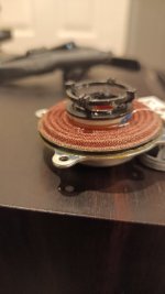
Ok .. So the matter of the concentrator has me exercised. I've made a point contact one, and a reduced size ring.
I don't need to test them because I can HEAR the hf drop. It's all very well to call it a low pass filter, in other words, an hf blocker/chopper, but WHY is this happening?
Ok again.. I tried them against the standard exciter ring and no doubt there's a difference.
What haven't we tried... Going the opposite way!...So I designed, for want of a better term, an expander. I boosted the contact diameter from 25 to about 35/40....
It sounds good... Needs testing, but it's worlds away from the concentrator...
See pic below... Eric, would be good if you could try it..It may not differ from the normal exciter-only mount, but who knows with this stuff... Can't put a screw through this though 😊
PS... My version has 4 point contact only... Not the whole ring, which is there just for structural purposes.
Eucy
Attachments
Last edited:
Thank you.Hi stereodreieck,
The panel is about 584 mm x 406 mm, and 2.1 mm thick. It has a frame around the perimeter and the panel is attached to the frame around most of the perimeter (except the corners) with Poron foam with very good (i.e. strong) damping properties. The panel has a 1.6 mm thick balsa core with about 0.23 mm carbon fiber epoxy skins. Below is the FR without EQ (dashed line) and with EQ (solid line). To be clear, my EQ is only bass and treble controls, which by chance happened to work pretty well with this panel.
Eric
View attachment 1418592
Hello Eucy,What haven't we tried... Going the opposite way!...So I designed, for want of a better term, an expander. I boosted the contact diameter from 25 to about 35/40....
Thank you for this feedback.
Here how I see the topic...
2 issues have been identified for a long time
- the resonance of the central area leading generally to a peak in the 10k. A counter measure seems to be a more rigid central area
- the famous "cavity noise" leading to a high SPL in the 2 to 5k to the rear. A supposed counter measure is to avoid the air in voice coil cavity to be compressed.
In parallel to that, we have had the information from Dave that the exciter ring acts as a low pass filter.
It is from all of that the concentrator allowing the air to flow more freely from the voice coil with a small interface diameter comes.
Our different tests show things are probably not that simple as nobody seems to report a full satisfaction from such concentrator.
What I have seen also from my directivity measurement is that the directivity in HF of the panel is linked to the ring diameter. I have only 13 and 25mm exciters. The 13mm has almost no directivity pattern where the 25mm shows a directivity from 8/10k. I guess a 32mm will have a directivity starting earlier.
Christian
This is similar to my 5 matchstick mountings.Ok .. So the matter of the concentrator has me exercised. I've made a point contact one, and a reduced size ring.
I don't need to test them because I can HEAR the hf drop. It's all very well to call it a low pass filter, in other words, an hf blocker/chopper, but WHY is this happening?
Ok again.. I tried them against the standard exciter ring and no doubt there's a difference.
What haven't we tried... Going the opposite way!...So I designed, for want of a better term, an expander. I boosted the contact diameter from 25 to about 35/40....
It sounds good... Needs testing, but it's worlds away from the concentrator...
See pic below... Eric, would be good if you could try it..It may not differ from the normal exciter-only mount, but who knows with this stuff... Can't put a screw through this though 😊
PS... My version has 4 point contact only... Not the whole ring, which is there just for structural purposes.
Eucy
The idea was to vent the coil area and minimise the problem of inwards firing high frequencies as shown in the second photo.
I did not follow on with this with measurements.
Maybe one day.
Steve.
Attachments

Hi Christian2 issues have been identified for a long time
- the resonance of the central area leading generally to a peak in the 10k. A counter measure seems to be a more rigid central area
- the famous "cavity noise" leading to a high SPL in the 2 to 5k to the rear. A supposed counter measure is to avoid the air in voice coil cavity to be compressed
Yes and yes. But... We also empirically considered that a 32mm exciter had a worse hf performance than a 25mm one.
Is that the case in your experience/tests? And Eric's vented concentrator actually made the 5k peak worse, but that was a frontal measurement I guess
The 8x8 mm contact concentrator has a distinct deadening effect on the hf, and it could be considered rigid in this zone, so increasing the rigidity appears to be an invalid protocol.
As the driven diameter increases, or the panel thickness decreases in the coil zone, I can envisage more of a pistonic tweeter action occuring, so the beaming does not surprise me, and it may not be deleterious to the overall panel performance.
It will be interesting to test the point contact vs a ring.
ie: a high cut filter. ..I would like to hear/see a theory as to why this happens. And what may happen if I make an even larger point contact connector.In parallel to that, we have had the information from Dave that the exciter ring acts as a low pass filter
Eucy
Last edited:
could you share your comments on how this configuration performed please?This is similar to my 5 matchstick mountings.
The idea was to vent the coil area and minimise the problem of inwards firing high frequencies as shown in the second photo.
I did not follow on with this with measurements.
Maybe one day.
Steve.
It might be floor and/or wall reflection cancellations.For a long time I have been aware that my "speaker lab" has a room mode that results in a dip in the FR at about 120 Hz. But now I'm starting to be aware of more of them. When I first measured the FR of the "4 exciter" panel in my previous posts (brown curve), I was al little surprised to see the three dips in the FR between 100 and 200 Hz. I was surprised because I expected that since I was only exciting the fundamental mode (up to about 600 Hz), I hoped for pretty smooth response in the 100 to 600 Hz region. As I mentioned, the 120 Hz dip didn't surprise me, but I didn't expect to see the other two dips.
But shortly after, I was looking at another, very different, panel and it had dips at the same 3 frequencies!
One panel is 2.1 mm carbon fiber/balsa, 584 x 406 mm, supported on 4 sides. The other is 5 mm plywood, 355 x 1200 mm and supported on only 2 sides. But the similarities in the FR seem too strong to be a coincidence.
Eric
View attachment 1418602
https://mehlau.net/audio/floorbounce/
Thomas
Sure, it was interesting to see that this is Ben Zenker's company, apparently. Probably just a distributor for billionsound exciters as well? I've met him several times at conferences, and he was always pretty enthusiastic about starting some kind of DML company. Maybe I can ask him to send me some of these.Regarding exciters to include, it would be nice to have the Xcite line of exciters as options. I'm eager to try out the new 19 and 25 mm versions myself, but have not bought any yet.
Yeah - right now I'm showing the average horizon-level acoustic response, but I can give the user a range of options.Could the lower frequency response curve be set up to have as an option to show a slice of the polar response at a selected angle?
Still just a thin plate model, I'm afraid!Finally, is you plate model based on a Kirchhoff-Love (thin plate) or Mindlin (thick plate) model? Or other?
Yep! The number of lobes is gonna be equal to the number of antinodes (peaks) in the mode. You often get mode shapes that are somewhat irregular, though, because of interaction with other nearby modes and the exciter, like the one below. The radiation lobes would be a fun visual to add to my software as well, and I definitely wrote code for that at some point back in the day.Is the number of lobes at each natural frequency directly related to the corresponding mode shape? And exactly how? It almost looks like the number of lobes might equal one of the mode indices. Is that right?
Oy, I really don't know. There might be some tricks I can pull that would simulate this, but I can't promise it would simulate the behavior that well.As you have now analysed the effect of the Dayton screw on adaptor at the rear of the panel, how difficult would it be to use your software to finally analyse the effect of adding a thin aluminium dome to the face of a timber panel (matching the coil diameter and without a hole behind it... I've used these on both ply and solid cedar panels)?
Indeed there is! And I wrote a paper about it back in the day. It's based on the idea of modal overlap - at low frequencies, modes are highly discrete, where at one frequency only one mode is contributing to the panel's velocity profile. At high frequencies, where no one mode has a majority influence over the velocity profile, we say that the panel has entered the "statistical" region, where the velocity profile looks like a pebble in a pond. This is usually good for omnidirectional radiation, but still doesn't save you from the coincidence frequency, unfortunately. I can probably add in a marker for that frequency as well. So now there will be three markers - coincidence frequency, unnamed cutoff frequency for the exciter ring/disc, and modal/statistical cutoff frequency.@EarthTonesElectronics
Dave,
In the surface velocity map. it there a way to distinguish between the situation at low frequencies, where the panel is mostly modal, and at high frequencies where the behavior is more like the "pebble in a pond"?
From a velocity map view, the appearance of both may be similar, but in fact they are quite different, I think.
That is to say, close to the fundamental of the panel, the velocity may be high near the exciter and low at the perimeter as a result of perimeter constraints. While at high frequency the (average) velocity be high near the exciter and low at the perimeter as a result of damping. Is there a way to depict at which frequency traveling waves become dominant over standing waves?
Thanks,
Eric
I'm paying attention to what everyone is saying about the exciter cavity noise as well - this isn't something I've ever considered, but it can definitely be added into my model for analysis. I'm curious to see if I can get the effects that everyone is measuring to appear in my simulations.
Hello Dave.
It is quite difficult to pinpoint the problems with the exciter noise.
Various noises could be caused by the spider, coil cavity, coil former breakup and of course, the inner surface area of the coil.
The material that the exciter is attached to could also cause problems .
For instance, eps is a very light material and produces large amounts of sound with very little effort, the exciter is hardly moving and under very little stress.
Now if we put the same exciter on a heavy panel material, such as thick ply, the exciter is now driving the panel very hard to try and reach the same volume levels .
The coil former, spider, and cavity resonance are being pushed to their limits.
I have in the past described this as being similar to headbutting an eps panel and then headbutting a brick wall , which would be the most painful 😳
The exciter will start to sound harsh, and if pushed further this can cause damage by stressing the former and coil glue and also the coil former foot, which I have had to glue back on a few times 🙄
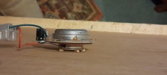
Strangely, the exciter in this photo seems to work better on thick heavy panel materials .
But not so good on lighter panel materials.
Is it because of its very robust build 🤔
I used the grey foam to dampen the coil former area that the mounting central bolt is joined to.
In the past I have described how to minimise the coil area surface problems on various panel material types.
But this only cures the problem within the inner surface of the coil and not always on the outer surface
Steve.
For some reason the photo would not upload?
It is quite difficult to pinpoint the problems with the exciter noise.
Various noises could be caused by the spider, coil cavity, coil former breakup and of course, the inner surface area of the coil.
The material that the exciter is attached to could also cause problems .
For instance, eps is a very light material and produces large amounts of sound with very little effort, the exciter is hardly moving and under very little stress.
Now if we put the same exciter on a heavy panel material, such as thick ply, the exciter is now driving the panel very hard to try and reach the same volume levels .
The coil former, spider, and cavity resonance are being pushed to their limits.
I have in the past described this as being similar to headbutting an eps panel and then headbutting a brick wall , which would be the most painful 😳
The exciter will start to sound harsh, and if pushed further this can cause damage by stressing the former and coil glue and also the coil former foot, which I have had to glue back on a few times 🙄
Strangely, the exciter in this photo seems to work better on thick heavy panel materials .
But not so good on lighter panel materials.
Is it because of its very robust build 🤔
I used the grey foam to dampen the coil former area that the mounting central bolt is joined to.
In the past I have described how to minimise the coil area surface problems on various panel material types.
But this only cures the problem within the inner surface of the coil and not always on the outer surface
Steve.
For some reason the photo would not upload?

I think you guys are onto something with the expansion of the contact area. It’s making a smaller diameter “tweeter/midrange” membrane in the middle. This smaller membrane has higher frequency modes. It would be good if the central membrane area was thinner - like doped fabric or maybe like a thin paper cone.
One could take this a step farther and use a commercially available full range driver that’s designed for backside mounting like a Vifa TC9FD and mount that to a panel with a 3in cutout hole. Then mount a bass exciter by double sided adhesive to drive the magnet and basket frame assembly of the TC9 so that it drives the main panel. What this will make is a coaxial 2-way DML. Probably XO will be needed but a quick test with see if this works could be easily done. The decoupling of function of the midtweeter and the main DML panel will free up the highs.
One could take this a step farther and use a commercially available full range driver that’s designed for backside mounting like a Vifa TC9FD and mount that to a panel with a 3in cutout hole. Then mount a bass exciter by double sided adhesive to drive the magnet and basket frame assembly of the TC9 so that it drives the main panel. What this will make is a coaxial 2-way DML. Probably XO will be needed but a quick test with see if this works could be easily done. The decoupling of function of the midtweeter and the main DML panel will free up the highs.
Last edited:
HelloIt is quite difficult to pinpoint the problems with the exciter noise.
I agree. There are probably different of the "cavity noise" (or "exciter noise"). I would even add to the list the obstacles on the trajectory of the sound like the exciter body, a possible spine that might cause diffraction. Seems more linked to the exciter, what is around than from the domain of the panel... Opinion. Hope to know more in the coming weeks.
Christian
- Home
- Loudspeakers
- Full Range
- A Study of DMLs as a Full Range Speaker